
Hardware
LoDi-RCS-Fun
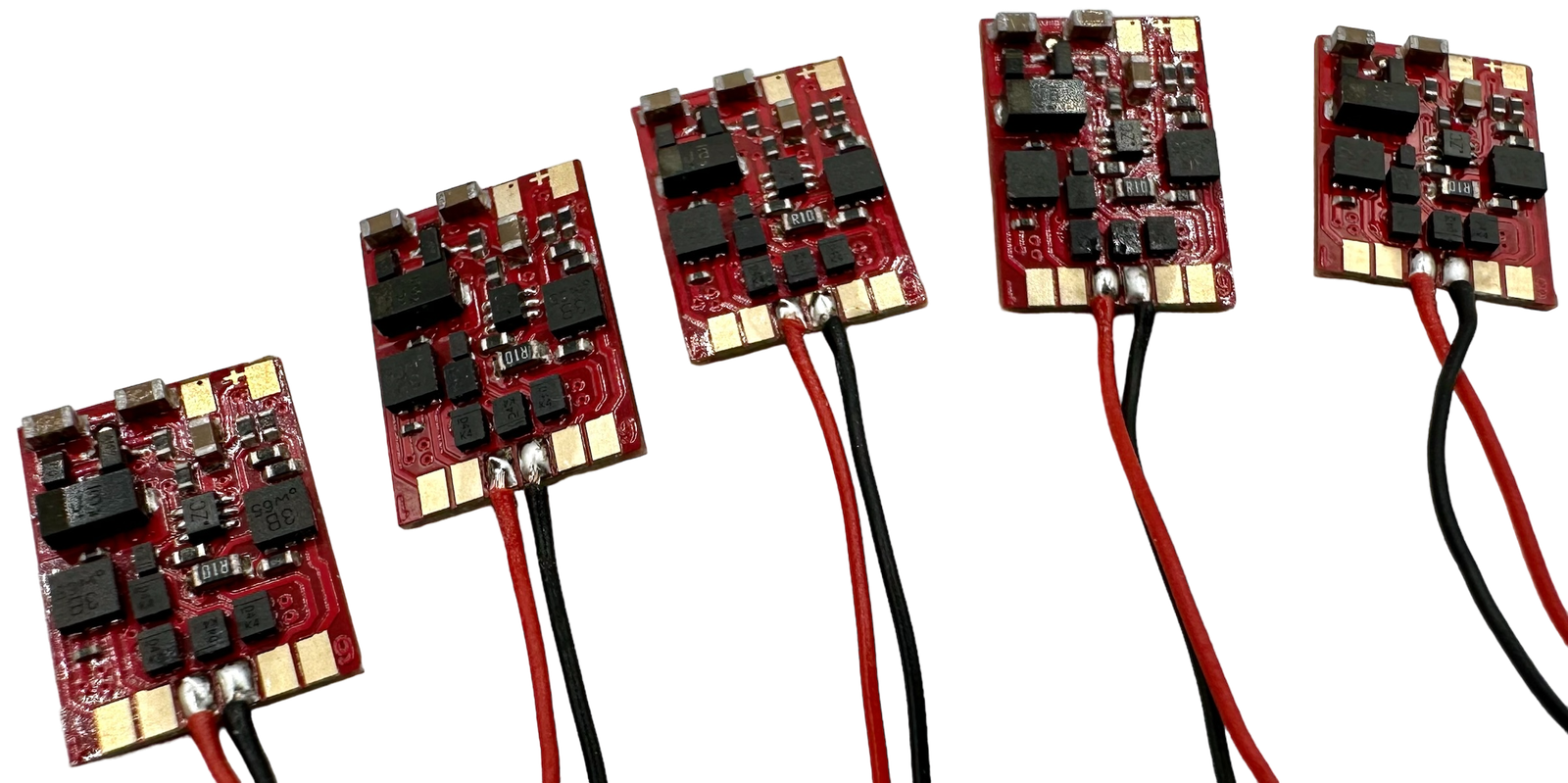
Extend what your model railway can do with the LoDi-RCS-Fun: a versatile RailCom transmitter and function decoder in one. Designed for locomotives without RailCom technology — certain Märklin models (MFX or DCC), for instance — the LoDi-RCS-Fun offers a simple retrofit that not only slots smoothly into the LoDi system but also provides eight additional switchable function channels for extended control. Compatible with DCC and MFX control systems, this decoder turns your locomotives into thoroughly modern, communicative and multifunctional models.
Features of the LoDi-RCS-Fun
- RailCom capability: supports bidirectional communication for RailCom capable feedback systems. Allows reports such as address, status or other specific data.
- Support for the Smart Power Pack (SPP): lets the decoder run for up to 15 seconds without track power. Configurable through CVs for an adjustable start delay and running time.
- A range of output effects: offers numerous lighting and function effects such as flashing, dimming and special effects. Effects are set individually for each AUX output through CVs.
- Programmability: supports CV programming on the main (PoM) (RailCom) and on the programming track. Allows addresses, configuration variables and firmware updates to be set.
- Flexible output configuration: up to eight AUX outputs for a wide range of applications. Outputs configurable for LEDs, SPPs and other accessories.
- Protection and safety functions: overload protection for the outputs. Supports temperature monitoring and signal quality checking.
- Compact build: suitable for use in almost every scale thanks to its small dimensions and high voltage tolerance.
1. Before we begin...
A few notes before we start the conversion...
Installing and fitting the decoder calls for a soldering iron, and particular care to avoid damaging the decoder. Take care that the connections do not touch conductive material directly, to avoid short circuits. The decoder must always be mounted so that there are no shorts to the body or to other boards. Where necessary, wrap the decoder in heat-shrink tubing.
If you can solder and have fitted a decoder or lit a coach before, the conversion should come easily. If you are a beginner, or would rather not attempt it, do contact our partners — they can fit the LoDi-RCS-Fun into your models quickly.
2. The LoDi-RCS-Fun and its connections
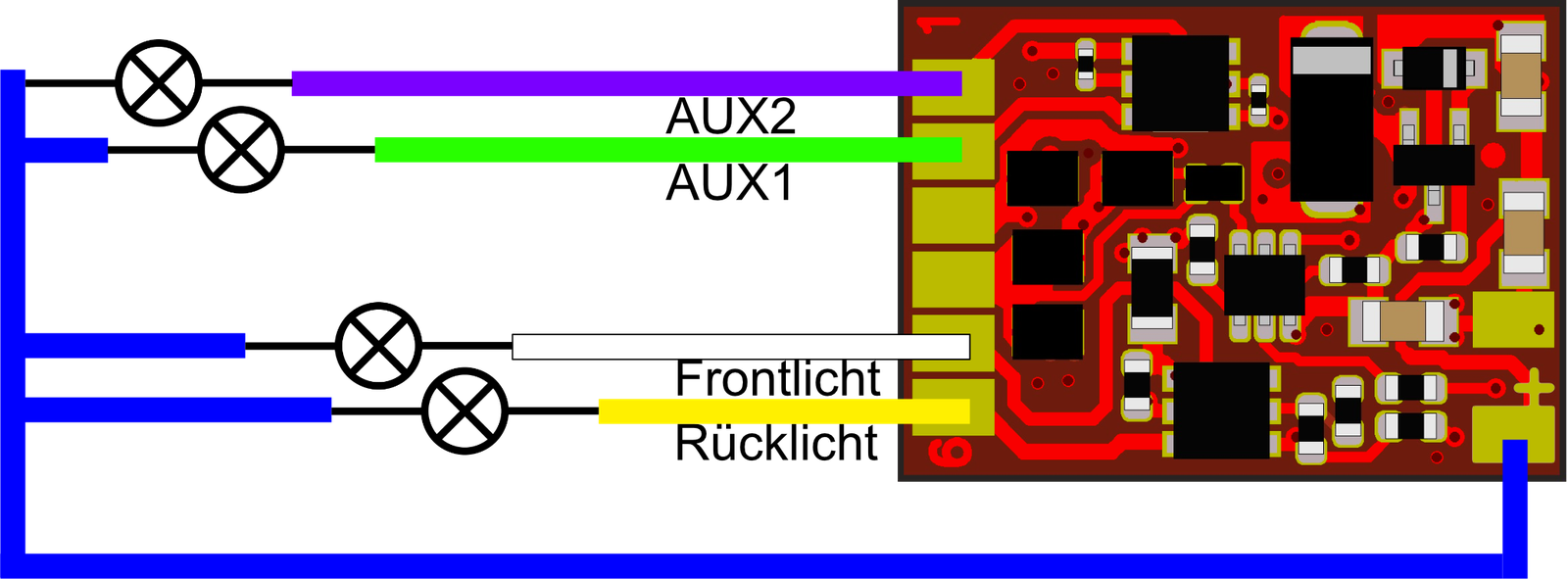
As described above, the LoDi-RCS-Fun has eight switchable AUX channels, of which F0V, F0R, AUX1 and AUX2 can each carry up to 250 mA. AUX3 to AUX6 are logic outputs and can each carry 10 mA. The total load on the decoder should not exceed 500 mA.
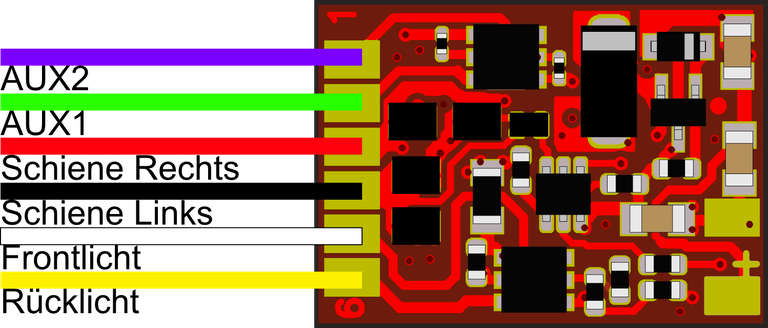
Two leads are already fitted to the decoder, one red and one black. That is the decoder's supply.
The decoder's numbering starts at 1.
- AUX1 and AUX2 = output switched by F1 as standard. Power output, up to 250 mA.
- Rail right = track connection to the centre rail or the right-hand rail.
- Rail left = track connection to the common or the left-hand side.
- Headlight and tail light = output switched by F0 depending on direction, power output up to 250 mA.
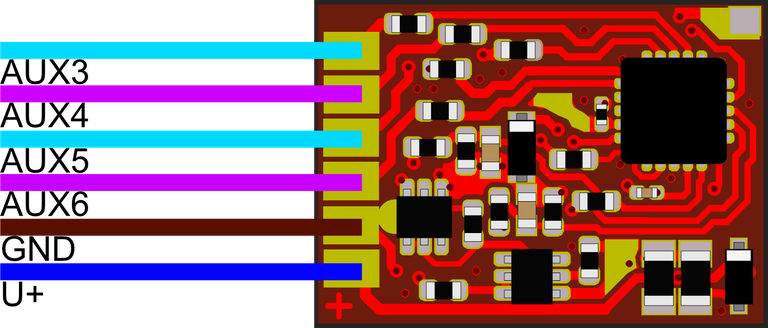
- AUX3 = logic output, up to 5 mA.
- AUX4 = logic output, up to 5 mA.
- AUX5 = logic output, up to 5 mA. Also used for SUSI.
- AUX6 = logic output, up to 5 mA. Also used for SUSI.
- GND = decoder common, connected to consumers that switch against the common. (AUX 3–6)
- U+ = decoder positive. Used for consumers that switch against positive (headlight, tail light, AUX1, AUX2).
3. Using the function outputs.
The LoDi-RCS-Fun is not only a RailCom transmitter, it is a full function decoder with plenty of AUX channels, four of which can carry 250 mA each. (No more than 500 mA in total.)
Another four AUX channels are available on the back of the decoder as described above. These are logic outputs and are used for SUSI, or for charging a power pack.
They can equally be used to drive an LED.
The outputs on the main connection side of the decoder are amplified, meaning they switch the negative. In our first example we now have four LEDs with a 1 kilohm series resistor each. If the FL, FR, AUX1 and AUX2 outputs are to run an LED, series resistors are essential.
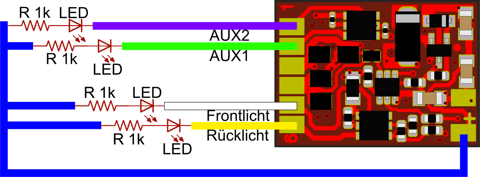
Lamps or other small consumers can of course also be switched on the FL, FR, AUX1 and AUX2 outputs.
These can be switched against the respective channel from the blue U+ or through the track common (or the locomotive body).
4. Fitting a LoDi-RCS-Fun into a locomotive
The LoDi-RCS-Fun has many uses; the additional AUX channels make it a good fit for coaches in particular. But it is primarily needed and used as a RailCom transmitter for locomotives in every scale. Many older decoders cannot do RailCom. If such a decoder works well but you still want RailCom, the LoDi-RCS-Fun is a good way to gain RailCom's advantages with that locomotive too.
Let us take a Märklin locomotive that handles DCC and mfx, and also Märklin locomotives that only handle mfx and should still be detected over RailCom by the control software. We will now explain the conversion step by step.
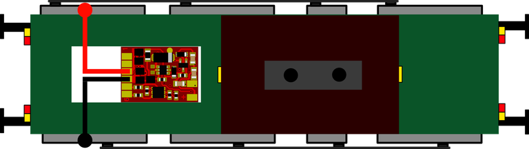
The LoDi-RCS-Fun is connected directly to the track, or to the vehicle's pickups, and is then — as the schematic shows — connected to the track without any additional components. There should also be no capacitors in the vehicle between rail right (usually the red wire) and rail left (usually the black wire).
We now have a small locomotive, a DHG 500, as a more recent example.
(For how to take the shell off your locomotive, please see the locomotive's own instructions.)
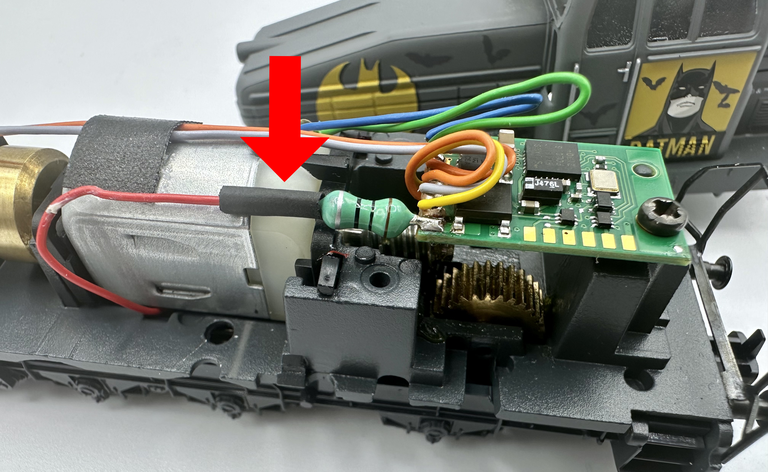
With the locomotive open, look for the wire connected to the centre rail pickup. In most cases that is a red wire. Here it is fitted to a choke. What matters now is that the LoDi-RCS-Fun must be fitted directly to the pickup. Slide the insulating sleeve back to do so.
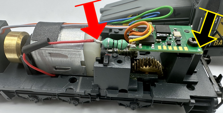
With the wire exposed, the red wire of the LoDi-RCS-Fun has to be joined to the red wire from the locomotive. The locomotive's common must also be joined to the black wire of the transmitter. That common is usually the locomotive body; on this locomotive it is very easy, because there is a solder point right at the screw. A continuity tester helps to find the common.
If you need help, do get in touch with us or with our service partners.
Next the LoDi-RCS-Fun is installed in the locomotive. Double-sided foam tape works best for that. In this case there is still enough room behind the cab. We stick the LoDi-RCS-Fun directly onto the existing decoder.
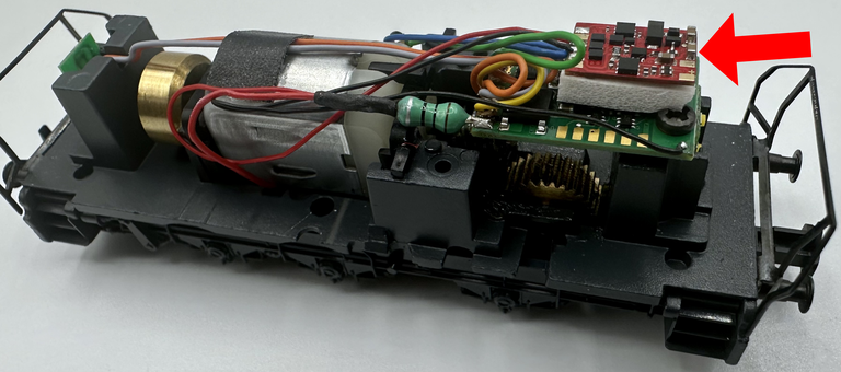
CAREFUL!
The decoder must be adequately insulated in every case. That is why heat-shrink tubing is supplied with our decoder. We chose not to wrap the decoder in it here, because it would have to be cut open again if further outputs or an electrolytic capacitor were to be connected.
5. Connecting a buffer capacitor or PowerPack (SPP) (optional)
An electrolytic capacitor or a PowerPack (SPP, Smart Power Pack) can be connected to the LoDi-RCS-Fun to support flicker-free running. This is optional and not needed if the LoDi-RCS-Fun is used purely as a RailCom transmitter.
To use an ordinary electrolytic capacitor there is a connection marked “+” on the back of the board. The GND (common) connection is beside it. Electrolytic capacitors between 220 µF and 2200 µF at 25 volts can be connected to these points. A charging resistor is already fitted on the decoder. The capacitor can be connected directly to the decoder.
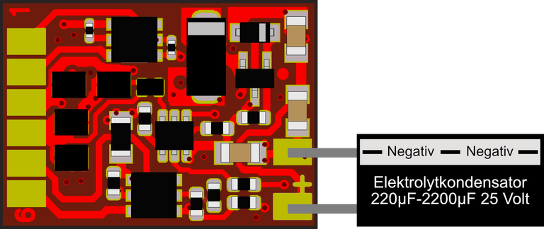
Please note that connecting an electrolytic capacitor can interfere with reading CVs on an ordinary programming output. RailCom is not affected by this limitation.
Smart Power Packs (SPP) let the LoDi-RCS-Fun stay powered for up to 15 seconds without power from the rails. That naturally depends on what the lighting draws and on the charge state of the capacitor.
To connect the PowerPack, use the three solder pads as shown in the photo. The white wire of the SPP can be connected to one of the logic outputs AUX3–AUX6. The red (V+) and black (GND) wires can be connected to the two V+ pads (on the underside) and the two GND pads (one below and one above).
The duration is set in CV222, in steps of 80 ms (default 255; CV value * 80 ms = 20 seconds). Once that time has passed without a track signal, the decoder switches all outputs off, even if the SPP is not fully discharged. The functions resume only once the track signal returns.
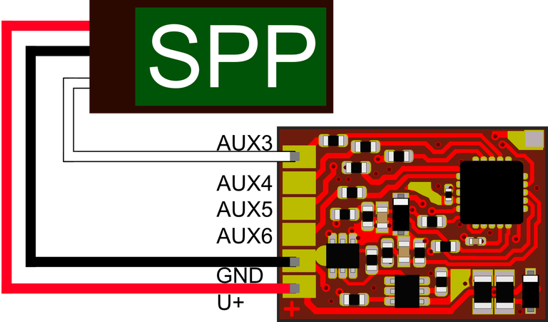
SPPs allow CVs to be read and written in the traditional way without having to be removed. Cutting the SPP source during programming happens automatically through the third wire (charge) of the FD Micro.
Once you have decided which output carries the charge connection to the SPP, effect 5 — that is, value 5 — has to be set on that AUX channel.
To avoid a very high draw when the booster power comes on while several SPP modules are in use, a start delay is strongly recommended (a different value for each decoder). The delay is set in CV221 in seconds and represents the time after which charging of the SPP module begins once the track is powered. When several decoders share the same track, these times should have different values so that not all SPPs start at once.
6. CV list, settings, addresses
The LoDi-RCS-Fun is configured through CVs.
The decoder can be programmed with any conventional command station that has a DCC programming output or handles PoM.
If you have a RailCom capable system, you can read the decoder's CVs live at any time.
With our equipment that means the LoDi-S88-Commander LX and the LoDi-8-GBM(-P), as well as the LoDi-CV-Programmer. Because the LoDi-RCS-Fun has a very extensive set of CVs, we decided to offer the complete list here as a download and to explain only the most important points on this page.