
Hardware
LoDi-RM-16+ v2
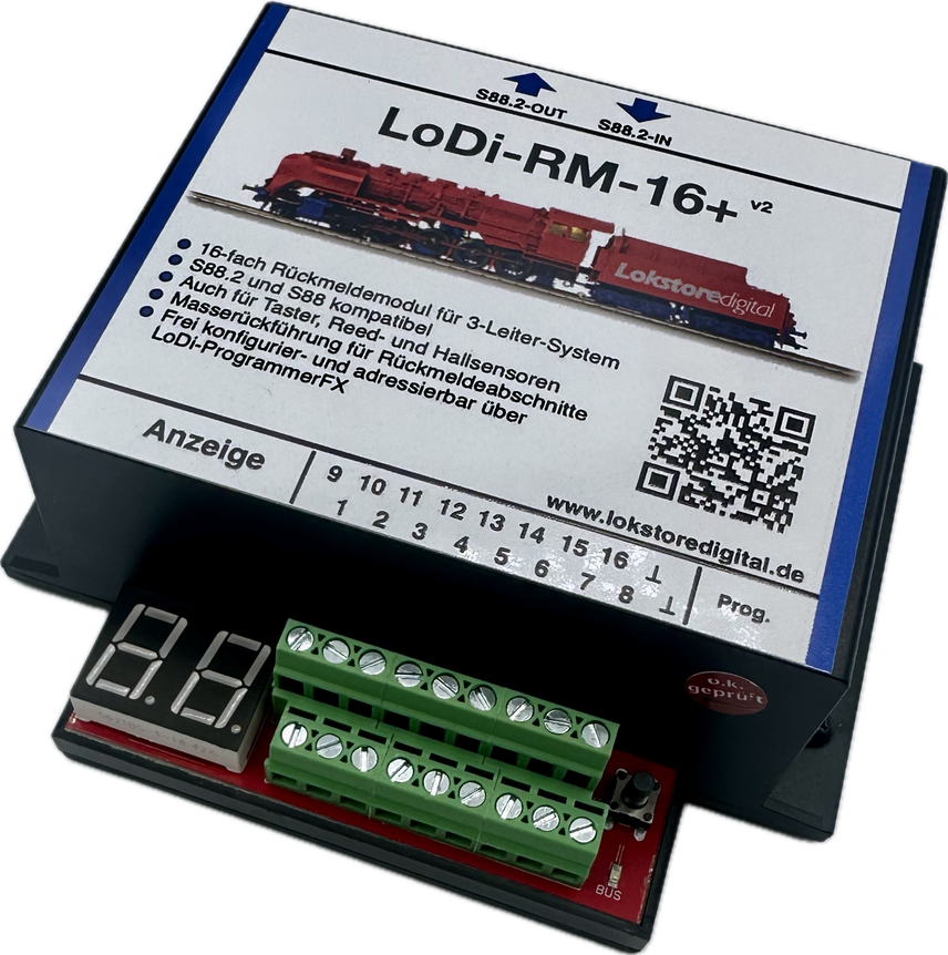
A simple feedback module for the three-rail system — one that returns the common straight back on the reporting side (the diode trick), with the trick built in, so to speak, and the usual characteristics of a standard feedback module.
Fitted with the new s88.2 bus, the odyssey of shifting addresses ends: a fixed address is assigned and stored in the device itself.
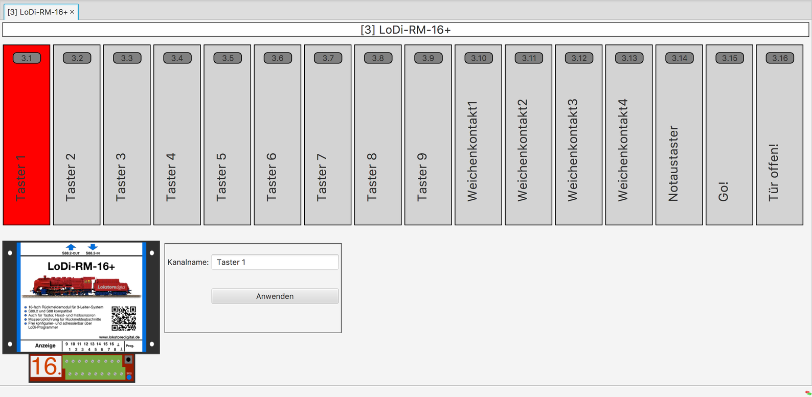
Every output can be given a name and, where the control software supports it, read out directly.
The LoDi-RM-16+ is also an excellent fit as a push-button detector, or for car systems working with Hall sensors or reed contacts.
Update late 2025: the LoDi-RM-16+ v2 remains essentially the same product — now with a modern 32-bit ARM CPU instead of an 8-bit AVR. Connections, protocols and behaviour are unchanged; existing installations work exactly as before. The new CPU brings shorter polling times and more robust signal detection. The module therefore gains performance and future-proofing without you having to change wiring or software.
Features of the LoDi-RM-16+ v2
- The LoDi-16-RM+ (v2) is a feedback module developed for use on the S88.2 or s88 bus.
- 16 feedback channels can be monitored per module.
- Built-in diodes allow the common to be returned to the separated reporting side on three-rail track. That means considerably better power supply to the locomotives within the detection section.
- The LoDi-RM-16+ (v2) is suitable for push buttons, Hall sensors, reed contacts and also turnout position feedback through limit switches.
- The LoDi-RM-16+ (v2) is easily configured through the LoDi-ProgrammerFX and has a display for checking the detectors directly and showing the module's address.
- Fully backwards compatible! The LoDi-RM-16+ (v2) can equally be run on s88N and, with an adapter, on an old s88 bus. There you will not have the full functions of the S88.2 bus, however.
1. The LoDi-RM-16+ v2 and its connections
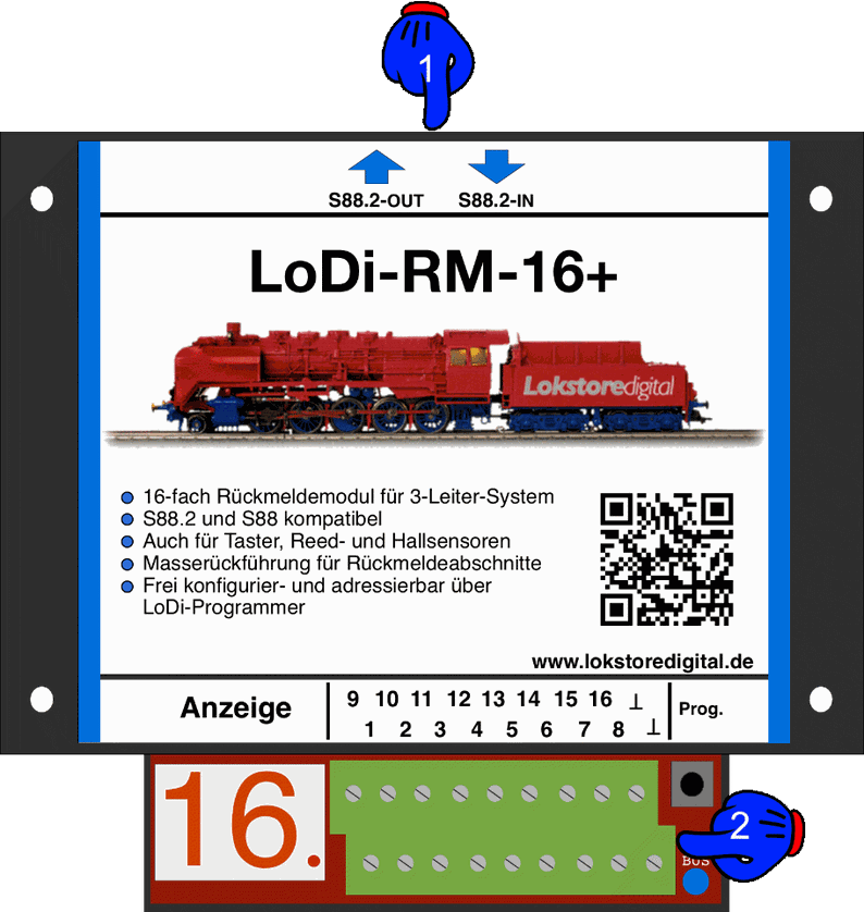
About the connections on the LoDi-RM-16+ (v2)
- (1): the S88.2 bus connects here. The S88.2-OUT arrow points towards the interface, since this is where the data from the track is reported back to the computer. The LoDi-RM-16+ (v2) is of course s88N compatible too; you can simply integrate it into existing layouts, but will then not have all the benefits of the new S88.2 bus.
- (2): the 16 detection sections connect here, along with the common for measuring or feeding into the reporting track.
2. The LoDi-RM-16+ v2 and its LEDs
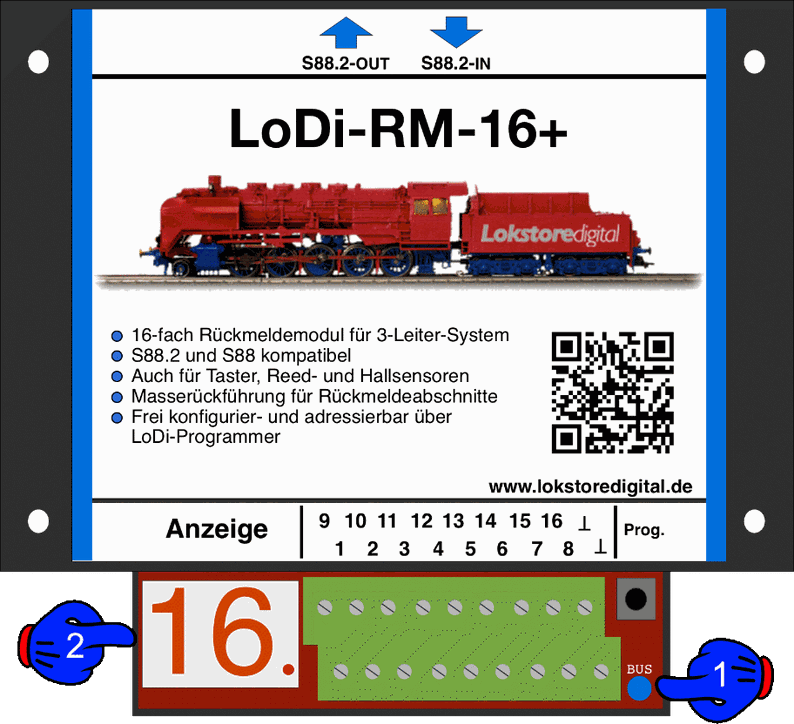
- (1) DCC LED and BUS LED: the bus LED lights as soon as the S88.2 bus is plugged in and supplied with power. The bus LED then glows a light blue.
- (2) Display: during operation this shows the detector currently occupied. The dot to the right of the number shows whether the module has detected the bus.
3. Connecting the LoDi-RM-16+ v2 to the S88.2 bus
As mentioned several times, the LoDi-RM-16+ (v2) carries the new S88.2 bus. That is provided by the LoDi-S88-Commander.
When the module is run on an S88.2 bus, the following features are available to you:
- Feedback from the individual blocks with a display
- Free naming of the individual feedback channels and of the LoDi-RM-16+ itself.
- Freely addressable! The module now keeps its address; there are no more shifts on the bus.
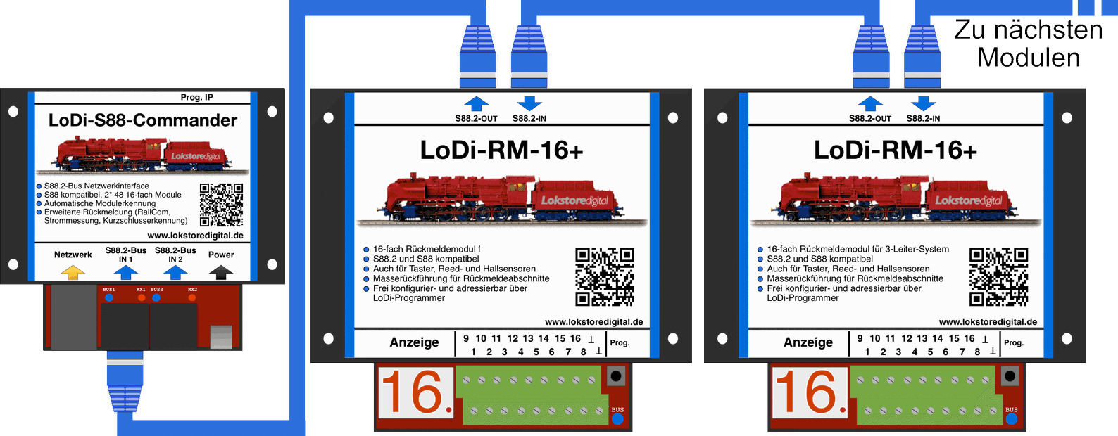
4. Connecting the LoDi-RM-16+ v2 to the s88 and s88N bus
The LoDi-RM-16+ (v2) is fitted with the new S88.2 bus, which does not mean the module cannot also be run on conventional command stations with s88 or s88N.
Feedback is available at all times. Addressing is assigned automatically over the s88 bus, as usual.
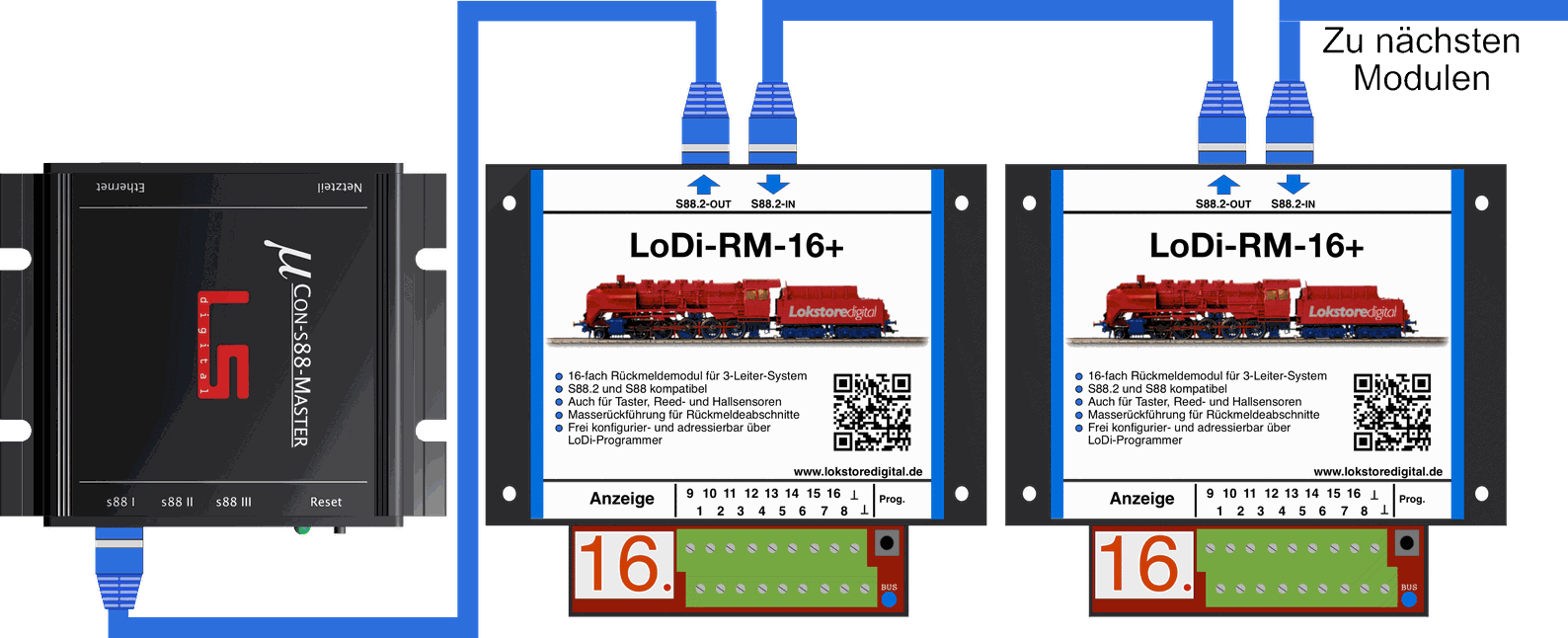
Here you see a LoDi-RM-16+ (v2) connected to a µCon-s88 master. It makes no difference whether the LoDi-RM-16+ (v2) units are connected to bus 1, 2 or 3; they behave like perfectly ordinary s88 modules.
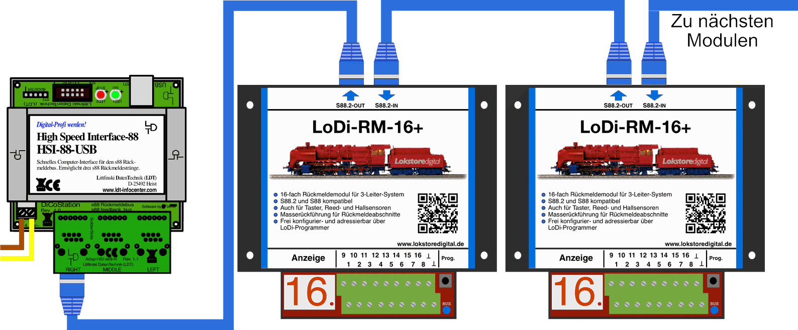
Here you see a LoDi-RM-16+ (v2) connected to an LDT-HSI. Any kind of s88N module can of course be hung in between.
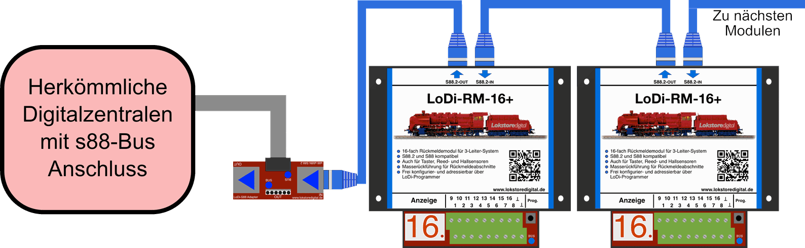
It is possible to connect the LoDi-RM-16+ (v2) to a conventional command station. To use the devices on an older station without the s88N connector, you need an adapter.
We offer the LoDi-S88 adapter for that, which can be used universally.
5. Connecting the LoDi-RM-16+ v2 to the three-rail track system
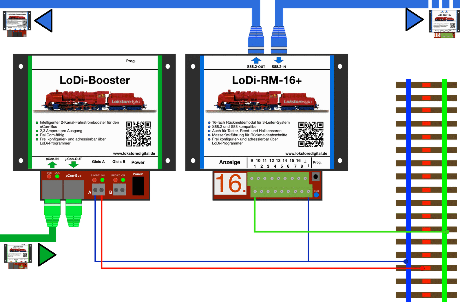
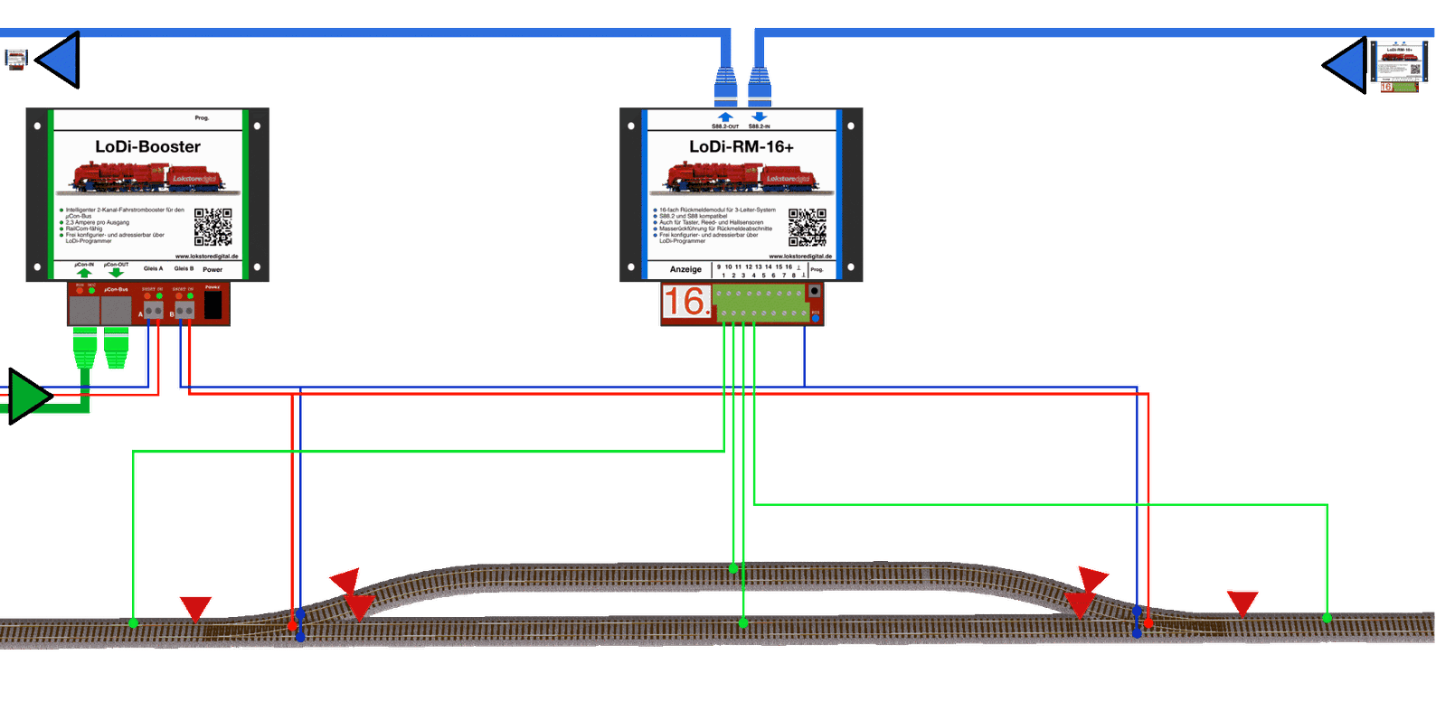
In this example you see the LoDi-RM-16+ (v2) connected to a common line coming from the booster, here the LoDi-Booster. The common line, which is also connected to the track, is joined to the inverted T on the LoDi-RM-16+, that is the common terminal.
Always watch for sufficient cable cross-section. We recommend avoiding a common line below 0.75 mm². Bear in mind that in the event of a short circuit the full short-circuit current has to be able to flow through the returned common.
The next example shows a small passing loop, fitted here with four detectors. We connected the booster to the centre rail and the common to the turnout entry and exit.
We also ran the common to the feedback module and to the earth symbol.
How many detection sections you need in a block depends on how many your control software requires. In this example we assume one per block; some software expects three per block, which increases the detector and wiring effort.
If you are unsure, do ask us or visit our LoDi forum, where there are always friendly helpers.
6. Connecting the LoDi-RM-16+ v2 to reed contacts and push buttons
As described, the LoDi-RM-16+ (v2) suits the use of reed contacts for the common car systems, or as a push-button input for any kind of button operation.
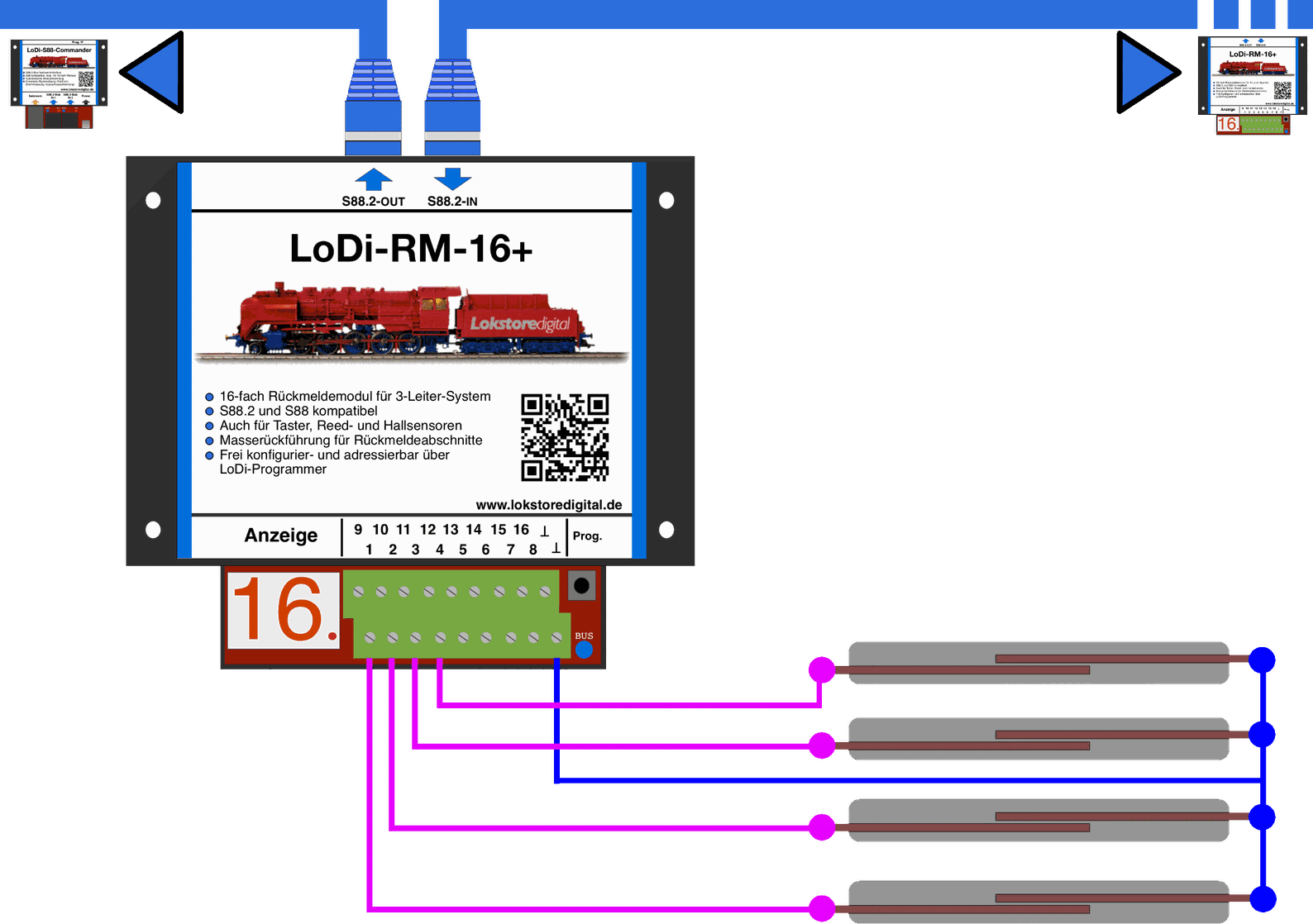
The following diagram shows a reed contact switched through the LoDi-RM-16+ (v2).
We simply short the earth contact (inverted T) on the LoDi-RM-16+ (v2) against one of the input channels 1–16 through the reed contact.
For simplicity we have shown only four reed contacts here, but 16 reed contacts can be connected to one LoDi-RM-16+ (v2) without trouble.
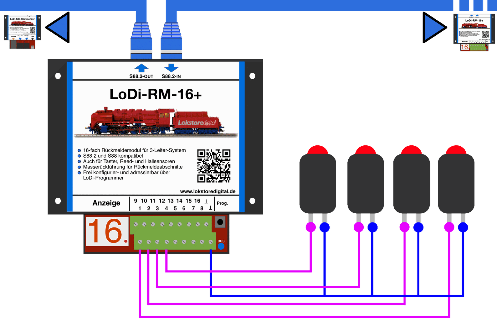
Push buttons are connected exactly as reed contacts are: a contact is shorted between earth (inverted T) and the respective channel 1–16. The device then triggers the report and sends that information over the bus to the interface.
7. Connecting the LoDi-RM-16+ v2 to Hall sensors
Hall sensors are modern magnetic switches that have to be fed from an external supply.
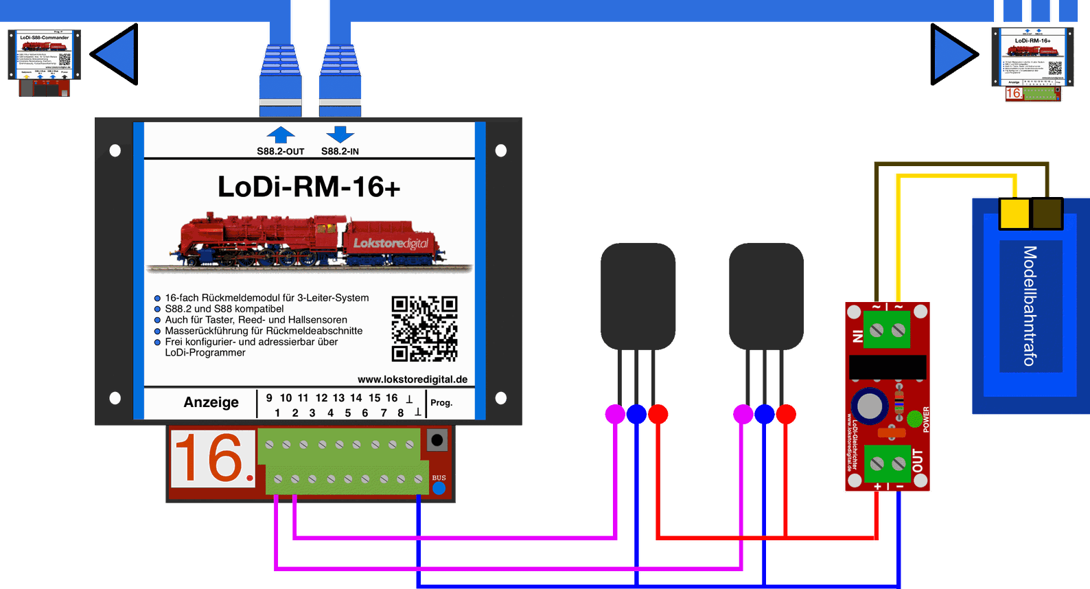
In our example the external supply comes from a conventional model railway transformer through a LoDi rectifier.
For that we connect the Hall sensors with the red wire, positive pole, to the LoDi rectifier.
The common, that is the blue wire, is connected from the LoDi rectifier to the LoDi-RM-16+ (v2). That is the opposite pole for the detector to measure the Hall sensors against.
Two Hall sensors are shown here; 16 per module can of course be run.
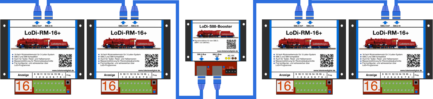
8. The LoDi-RM-16+ v2 with a LoDi-S88-Booster
At some point there simply is no current left...
If you run more than 12 modules on one bus, a LoDi-S88-Booster would be advisable; it not only supplies the modules with fresh current, it reconditions the data as well.
9. Technical data
| Property | Value |
|---|---|
| Dimensions | Length 130 cm |
| Width | 115 cm |
| Height | 4.5 cm |
| Weight | 167 grams |
! ! ! Careful ! ! ! The S88.2 bus may only be run at 5 volts. Do therefore check what voltage your S88 bus runs at. ! ! ! Careful ! ! !
At the digital terminal the detector can be supplied with 12 to 24 volts.
Do mind the specifications of your command station or booster manufacturer here.
Loadable by consumers with 5 amperes briefly and 3 amperes continuously per output.
Suitable for every common scale.
10. Setting up the LoDi-RM-16+ v2 in the LoDi-Programmer
Here is how to set up the LoDi-RM-16+ v2
11. LoDi-16-RM+ PDF download
Here you can download a summary of the LoDi-RM-16+ hardware and software as a PDF.