
LoDi-Con manual
Building track plans
The track diagram shows an area — a station, for instance — as a grid of track elements. It lets you throw turnouts and set signals. Occupancy is marked by colouring the track in question. Where local RailCom detectors are active, the address of the locomotive can be shown in a block field, and the locomotive can be taken onto the throttle from there.
Any number of track diagrams can be created. A diagram can be between 10x8 and 50x50 elements in size. The visible area covers 10x8 elements; in larger diagrams it can be moved with your finger.
Opening a track diagram
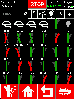
Track diagrams are opened from the accessory screen, where they are always shown ahead of every other accessory. Clicking the icon of a diagram opens it.

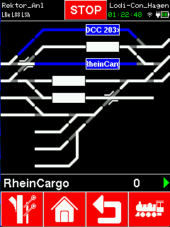
The track diagram is drawn as a grid. Where occupancy detectors are assigned, the tracks turn blue when occupied. Where RailCom-capable feedback modules are fitted, an occupied block shows the train name, provided the locomotive is RailCom-capable too.
Turnout elements that carry an accessory are drawn in their current state. Clicking a turnout element throws that turnout.
RailCom-capable locomotives can be selected by clicking the block directly. If the locomotive is not registered with the command station yet, it is created automatically.
Switching between track diagram and locomotive is possible straight from the two red buttons: accessories (bottom left) and locomotive screen (bottom right).
Creating a track diagram
Creating one from the accessory screen
1. Select the red accessory icon at the bottom left.
2. Press the '+' key at the top right.
3. In the menu that appears, choose "Track diagram"
4. After you are asked for a name for the diagram, it is created.
Creating one from the article database
1. In the main menu, choose Article database.
2. Select the "[New]" entry.
3. In the menu that appears, choose "Track diagram"
4. After you are asked for a name for the diagram, it is created.
Editing a track diagram
After a track diagram is created, edit mode is already active. It can also be activated from the accessory screen by long-pressing the icon of the diagram.
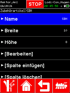
Name
The name of the track diagram can be changed under this entry. It may be up to 32 characters long.
Width
The width of the track diagram can be set between 10 and 50 columns. Elements outside that range are not shown.
Height
The height of the track diagram can be set between 8 and 50 rows. Elements outside that range are not shown.
[Edit]
The edit entry lets you add, change and delete track elements. For a better overview the diagram is drawn with a grid. The current cursor position is shown at the top right. The cursor can be moved by tapping the touch screen as well as with the rotary control.
Pressing the rotary control, or tapping, either creates a new element or starts editing an existing one.
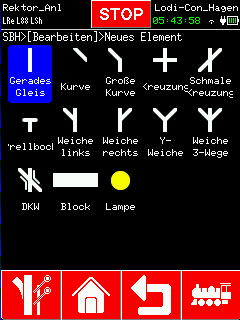
Clicking an empty element brings up a selection screen offering every permitted element type. Clicking one of them selects that type and the display returns to the track diagram, where the orientation can be changed with the rotary control. Pressing the control places the element.

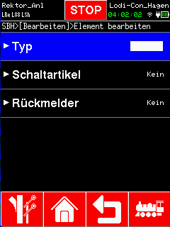
Clicking an existing element brings up its settings menu.
- Type: change the element type and its orientation.
- Accessory: choose the accessory to be switched when the element is clicked. Turnout streets can be given here as well.
- Feedback: assign a feedback module to the element. Every element can respond to feedback with a change of colour, which is how occupied track is shown. The block element additionally shows the locomotive name when the occupancy detector is RailCom-capable.

[Insert column]
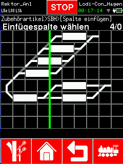
This menu entry inserts columns into the track diagram. The green line marks the insertion point; it can be moved with the rotary knob or by tapping the diagram. After confirming with the knob, every element to the right of the green line moves one position to the right and the diagram grows by one column.

[Delete column]
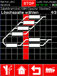
This menu entry deletes columns from the track diagram. The red line marks the deletion point; it can be moved with the rotary knob or by tapping the diagram. After confirming with the knob, every element coloured red is deleted and every element to the right of the line moves one position to the left. The diagram shrinks by one column.

[Insert row]
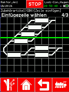
This menu entry inserts rows into the track diagram. The green line marks the insertion point; it can be moved with the rotary knob or by tapping the diagram. After confirming with the knob, every element below the green line moves one position down and the diagram grows by one row.

[Delete column]
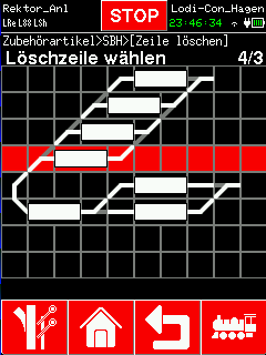
This menu entry deletes rows from the track diagram. The red line marks the deletion point; it can be moved with the rotary knob or by tapping the diagram. After confirming with the knob, every element coloured red is deleted and every element below the line moves one position up. The diagram shrinks by one row.

[Delete track diagram]
This menu entry deletes a track diagram.

Would you like to see the quality of the devices for yourself?
Get in touch with us HERE!
Visit our forum, where experienced users are happy to help you.