
Hardware
LoDi-Dual-Servo-DCC-H
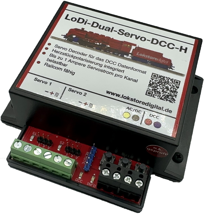
The dual servo decoder, for when it may be a little bit more . . .
Fitted with a large power section, it is designed for small to large servos.
Over RailCom the decoder can be read quickly and its CVs configured.
Thanks to the built-in frog polarisation, no further hardware has to be bought.
It can also be run analogue, on DC or AC.
Features of the LoDi-Dual-Servo-DCC-H
- A two-channel servo decoder for servos drawing more than 1 ampere. (2.5 amperes maximum in total.)
- With built-in frog polarisation for the frogs of the turnouts.
- The decoder listens to the DCC format and can be read and configured over RailCom.
- The servos can also be set without CVs, through the buttons or an external servo remote.
- Also usable stand-alone with DC or AC!
- A connection for a servo remote to set the servo positions.
Videos about the device from YouTubers
Here we show contributions from customers who use LoDi devices and have taken the time to create tutorials.
1. The LoDi-Dual-Servo-DCC-H and its connections
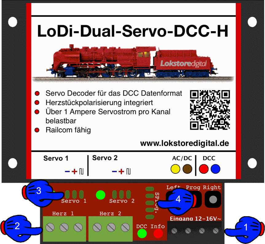
- (1) Connection to the transformer as well as to DCC, that is to a booster, feedback module or directly to a command station.
- (2) Connection of the turnout frogs
- (3) Connection for servos with a 3-pin plug.
- (4) A three-button remote can be connected here for external control. Beyond that the pin connector can also be used for external buttons on a control panel.
2. LEDs and buttons on the LoDi-Dual-Servo-DCC-H
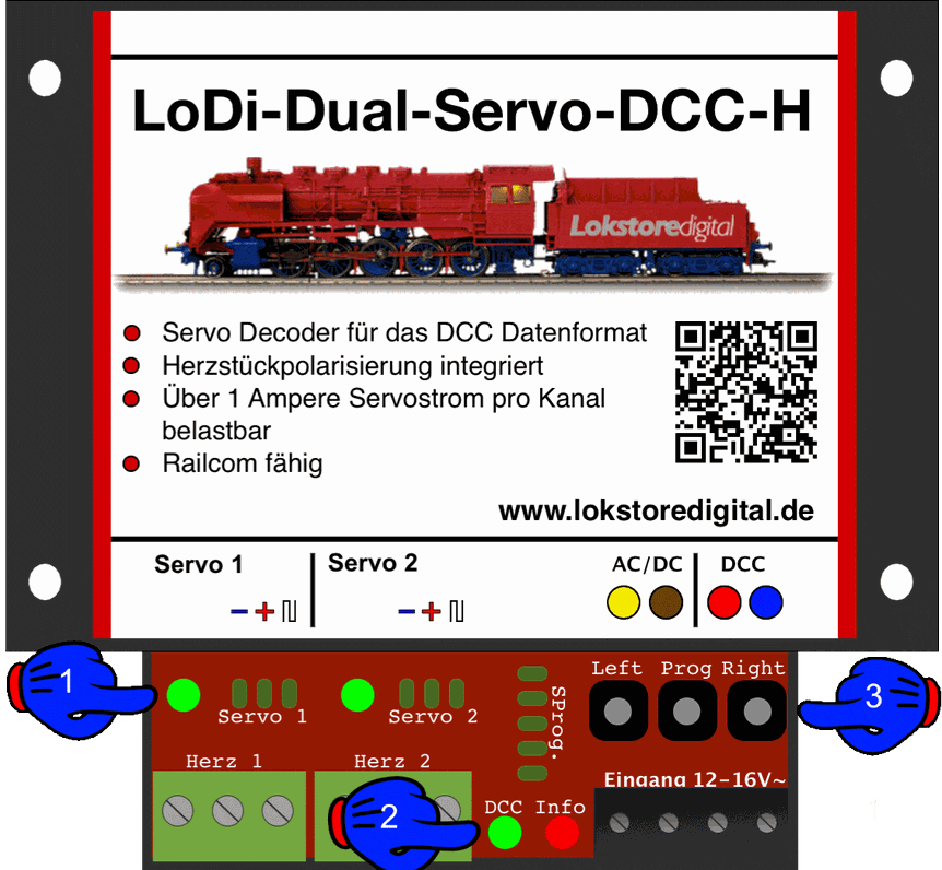
- (1) Servo LEDs; they show whether the servo is powered, or whether it is being addressed.
- (2) DCC (green LED) lights as soon as a DCC signal is present at the decoder. The info LED (red LED) lights as soon as voltage is present at the decoder. The info LED also flashes on a valid command, and to acknowledge reading or writing CVs.
- (3) Buttons for manual operation and for setting the DCC address and the servos.
3. Connecting a transformer and DCC
There are several ways of supplying the LoDi-Dual-Servo-DCC-H with power.
With servos that draw a lot of current, or servos that have to hold a sprung turnout blade constantly, the following variant is advisable.
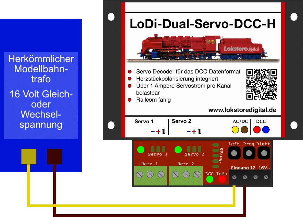
The transformer shown here could equally be a DC supply, but please take care that the operating voltage lies in the range of 10–22 volts DC.
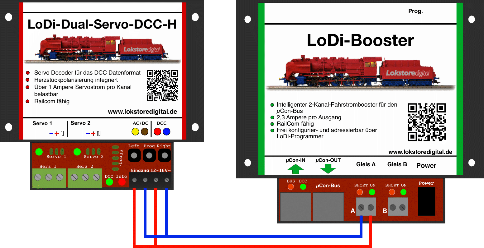
Once the decoder is supplied with power, it has to be able to receive its data. For that the decoder has to be connected to a command station or a booster. In the example here we use a LoDi-Booster.
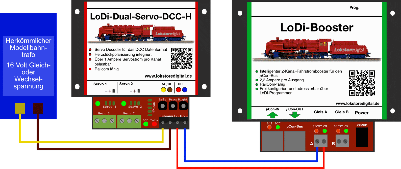
CAREFUL! For reliable switching of DCC accessories, a separate circuit or booster output should always be used.
If you only use small modelling servos, or switch the servos off once they have moved, the LoDi-Dual-Servo-DCC-H can be used directly from a booster without trouble.
A LoDi-Booster, for instance, provides 2.3 amperes, which is enough for up to 15 decoders. A single small servo usually draws no more than 100 mA. With DCC, switching commands are always processed one after another.
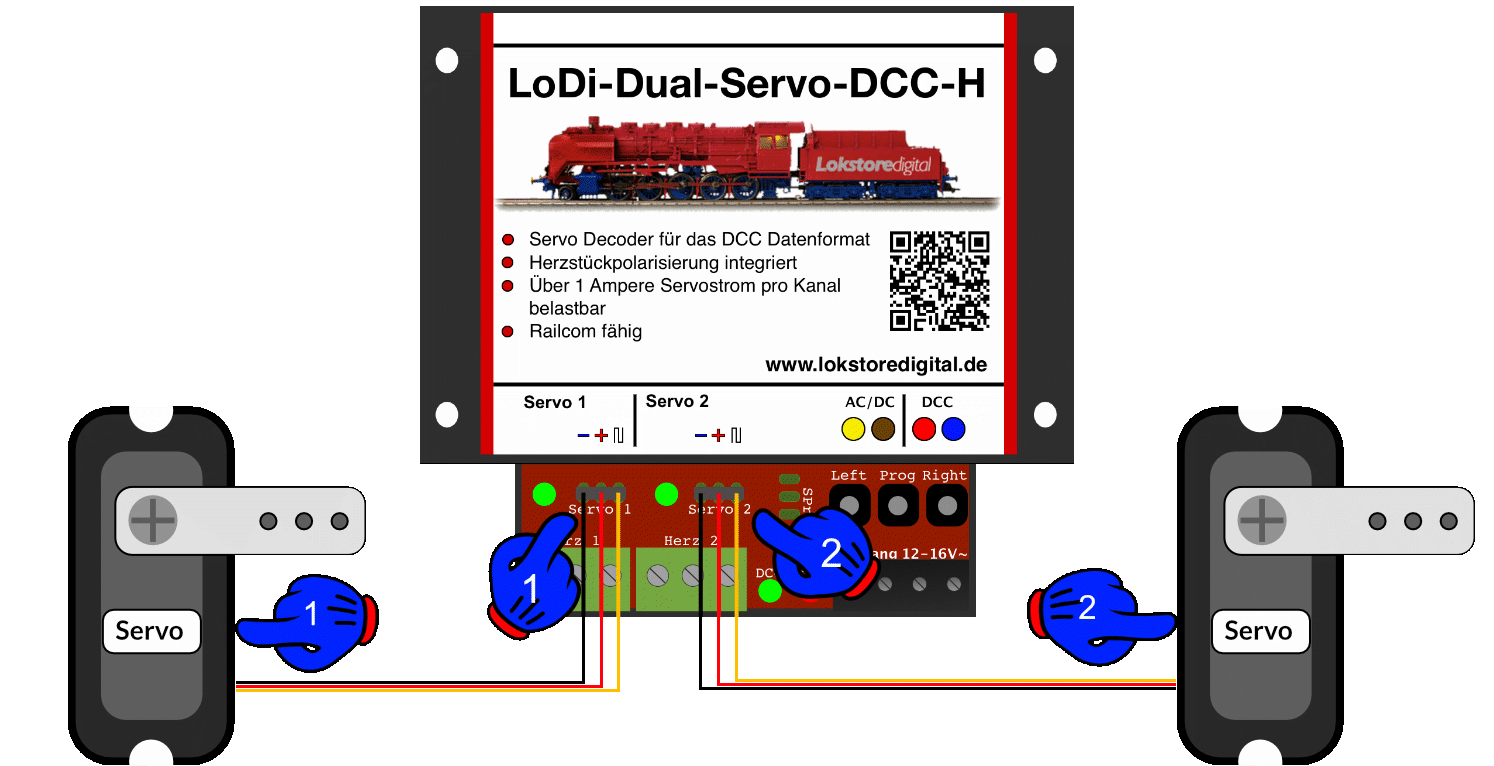
4. Connecting the servos
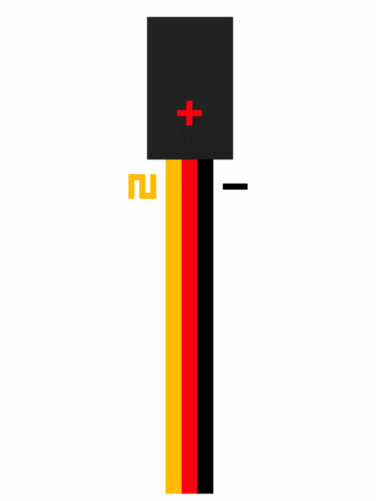
In most cases a servo has a cable with three conductors.
These are:
- Yellow or orange, which carries the data signal
- Red, carrying 5 volts, which supplies the servo with the voltage it needs.
- Black or brown, which carries the servo's common.
The colours can differ further, so check your servo's documentation if you are unsure.
At (1) and (2) you see the connections for the servos on the decoder. Negative is on the left. The socket is pushed straight onto the decoder's pins.
5. Connecting the frogs
With turnouts in two-rail systems, many track systems call for frog polarisation, because the polarity of the frog changes when the turnout blade is thrown.
To take care of that switching, the LoDi-Mono-Servo-DCC-H has a built-in relay that reverses the polarity at a turnout's frog.
This switching point can also be adjusted through a CV if wanted.
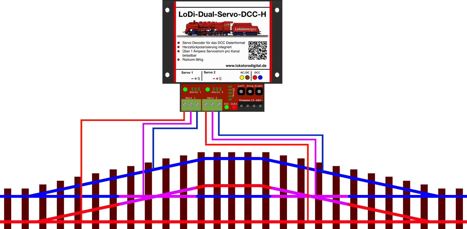
This picture shows the arrangement of two connected turnouts whose frogs have to be reversed.
(shown here in pink)
If the polarity of the frog is wrong, or there is a short circuit when the locomotive runs onto the frog, the connecting lead would strictly speaking have to be swapped. You can however simply swap the relay setting in CV 108 or 109.
6. CV list and settings
The LoDi-Dual-Servo-DCC-H is set through CVs.
If you have the LoDi-Rektor with a LoDi-Booster or CDE booster connected, you can write the CVs over PoM (programming on main) with the LoDi-ProgrammerFX from version 2.2.
The decoder can equally be programmed with any conventional command station that has a DCC programming output or handles PoM.
If you have a RailCom capable system, you can read the decoder's CVs live at any time.
Setting the DCC address: you have now installed the decoder successfully, the DCC cable is plugged in, and the LoDi-Dual-Servo-DCC-H now glows red continuously to show it is ready.
As delivered, the decoder responds to turnout or accessory address 1.
If you want to change an address quickly, proceed as follows: there is a programming button on the decoder as described above. Press it for 3 seconds. The info LED starts to flash quickly, telling you the decoder is ready for a new address.
Now send the new address from the control software, directly at a command station or in the LoDi-ProgrammerFX (the LoDi-Rektor is required), in the turnout field under DCC.
The decoder takes the address, the info LED stops flashing and glows steadily again. It is now reachable at the address you chose.
Setting the CVs: as mentioned several times, the LoDi-Dual-Servo-DCC-H can be programmed over PoM (programming on main). In most applications there are three CVs per servo to consider.
1 × position A = CV 33, value 0–255
2 × position B = CV 34, value 0–255
3 × speed = CV 41, the speed at which the servo moves, 0–255
These values can be read back later over RailCom.
7. Setting the servos with the buttons and the remote
The decoder has three buttons; the Prog button sets the address quickly, as mentioned above.
The Left and Right buttons can be used for quick manual operation, or for fine-adjusting the servos.
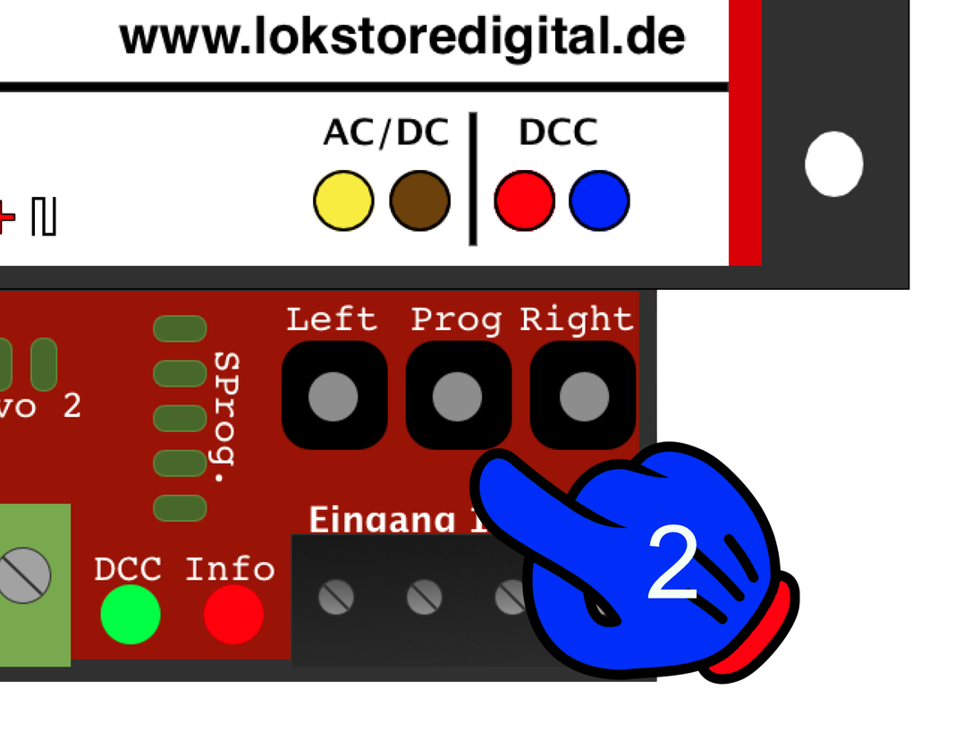
Proceed as follows: press the Prog button for 3 seconds, as you would to programme an address.
The info LED now flashes quickly again. The decoder could now also receive a new address.
Press the Prog button again straight away; the LED for servo 1 should now flash in addition to the INFO LED
(yellow LED).
By flashing, the yellow LED tells you that servo 1 can now be set.
The servo should also have moved to position 1. With the Left and Right buttons the position of servo 1 (Pos 1) can now be set. If Pos 1 is right, press the Prog button again to reach Pos 2. Set that with Left and Right as well.
Next the speed of servo 1 can be set; servo 1 travels between the positions you set. Pressing Left makes it faster, pressing Right makes the servo move more slowly.
Once the speed is right, servo 1 is fully set.
Now press the Prog button again and the decoder moves to servo 2. Repeat the steps above. After setting the parameters for servo 2, pressing the Prog button returns the decoder to normal mode.
If you want to test the servos again quickly, a short press on Left or Right changes the position you set for servo 1 or 2.
The decoder has a 5-pin programming output which can be used for a remote. If you have installed the decoder under the layout, for instance, the remote is very helpful when setting the servo positions.
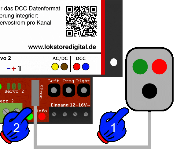
8. Stand-alone version
Thanks to the stand-alone version, the decoder can be supplied with ordinary DC up to 22 volts and AC up to 16 volts.
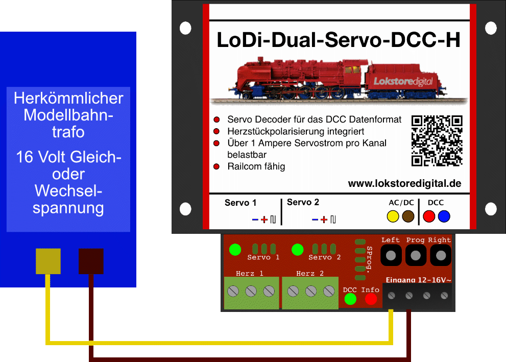
External buttons can be connected through the Remote connections (shown in the picture as SProg.), those of a track diagram panel, for instance.
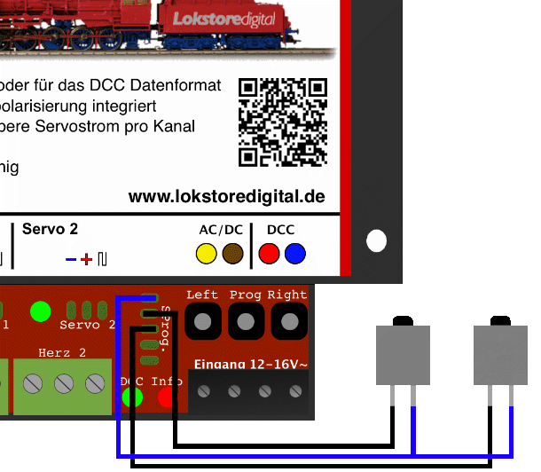
Here you see an example of the two external buttons connected. The blue lead is the shared common; the two black ones are the control leads for servos 1 and 2.
9. Technical data
| Property | Value |
|---|---|
| Dimensions | Length 8.9 cm |
| Width | 10 cm |
| Height | 3.5 cm |
| Weight | 97 grams |
In digital operation the decoder can be supplied with up to 22 volts.
Do mind the specifications of your command station or booster manufacturer here.
The decoder can be run on 20 volts DC or 16 volts AC.
Loadable by servos with 3 amperes briefly and 2.5 amperes continuously.
Frog polarisation loadable with 4 amperes per output.
10. LoDi-Dual-Servo-DCC-H PDF download
Here you can download a summary of the LoDi-Dual-Servo-DCC-H hardware as a PDF.