Hardware
LoDi-Operator 16-SD-FL (1k)
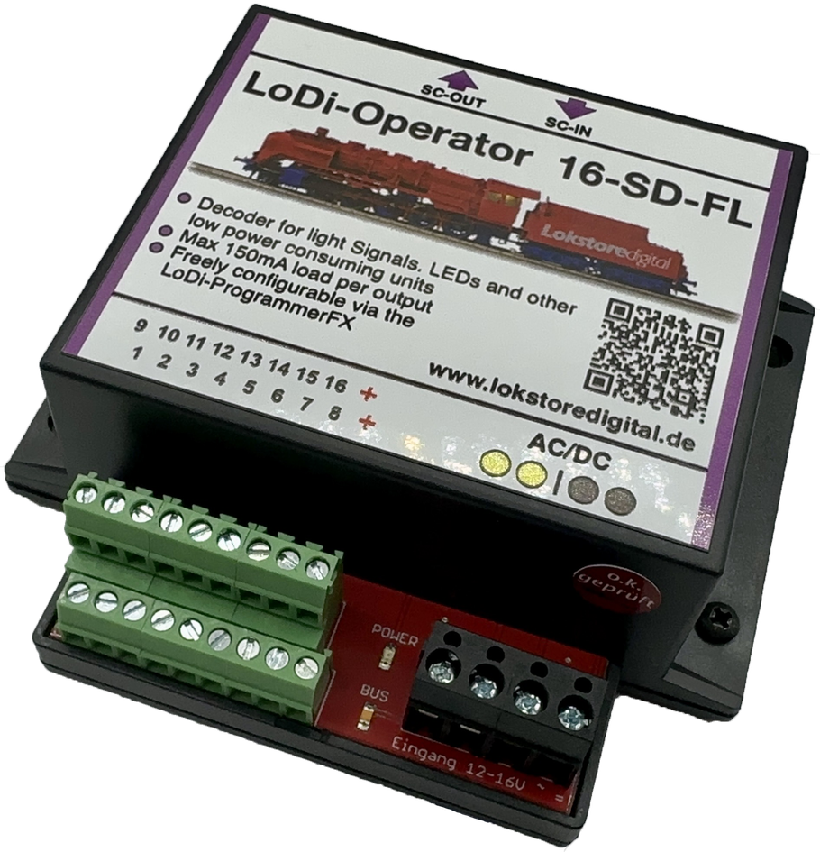
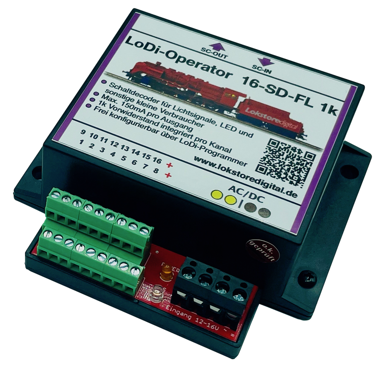
The LoDi-Operator 16-SD-FL is a powerful switching decoder with 16 outputs in total, each providing 150 mA. This switching decoder is the perfect complement to the LoDi-Shift-Commander and is ideally suited to all kinds of light signals, LEDs, lamps and small motors. Thanks to the optional 1k version, LEDs can be connected quickly and easily without needing a series resistor.
Configuring the LoDi-Operator 16-SD-FL could hardly be simpler, thanks to the user-friendly LoDi-ProgrammerFX. That software lets you adjust the settings of the LoDi-Operator 16-SD-FL easily and quickly.
Features of the LoDi-Operator 16-SD-FL (1k)
- A DC decoder for the SC bus, for connection to the LoDi-Shift-Commander.
- Sixteen channels are available, each with 150 mA per output; the total of the connected channels must not exceed 2 A.
- You can connect light signals, LEDs, lamps, smaller motors, MP1 and MP5 as well as many other smaller loads to the LoDi-Operator 16-SD-FL.
- Easily configured with the LoDi-ProgrammerFX.
- In the LoDi-Operator 16-SD-FL 1k version with an integrated 1k resistor. That way LEDs can be connected directly to the decoder.
1. The LoDi-Operator 16-SD-FL (1k) and its connections
The LoDi-Operator 16-SD-FL (1k) is a switching decoder connected to the LoDi-Shift-Commander. It can be run on the slow and on the fast bus.
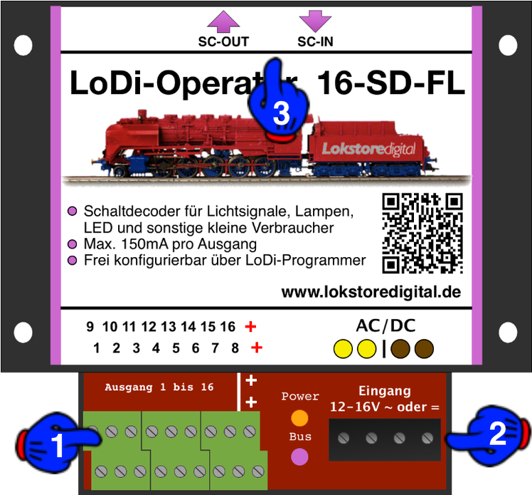
About the connections on the
LoDi-Operator 16-SD-FL (1k)
- (1) Here you can connect loads such as light signals, lamps and so on; you will find more on this in the wiring examples.
- (2) The AC/DC model railway transformer is connected here. IMPORTANT! Please only use authorised model railway transformers.
- (3) The SC bus from the LoDi-Shift-Commander is connected at the SC-OUT and SC-IN sockets. More on this in the section on connecting to the SC bus.
2. LEDs on the LoDi-Operator 16-SD-FL (1k)
The LoDi-Operator 16-SD-FL (1k) has two LEDs to help you recognise the state of the device and understand faults more quickly.
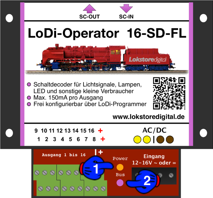
- (1) This LED lights when you connect the transformer voltage to the socket
- (2) The bus LED lights as soon as the SC bus coming from the LoDi-Shift-Commander is plugged in and that unit is powered.
3. Connecting the LoDi-Operator 16-SD-FL (1k) to the SC bus
The LoDi-Operator 16-SD-FL (1k) is connected to the SC bus coming from the LoDi-Shift-Commander.
You can see this in the first wiring picture here.
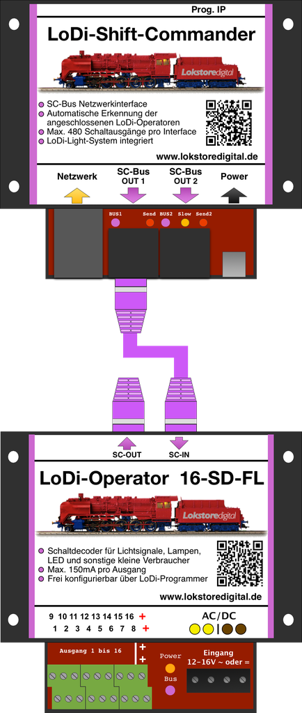
In this picture you see the LoDi-Shift-Commander together with the decoder connected to it, here the
LoDi-Operator 16-SD-FL (1k).
The decoder is connected to SC bus Out 1. 96 outputs are available here.
On the LoDi-Operator 16-SD-FL (1k) you can use the connections as your layout requires. It does not matter whether you first connect a
LoDi-Operator 16-SD-FL (1k) or a LoDi-Operator 4-WD-DC or AC.
The LoDi-Shift-Commander is able to detect the connected decoders.
You can then programme the assignment with our tool, the LoDi-ProgrammerFX
configure.
The bus has to be terminated at the last operator.
That means you always have to plug the terminating plug, called the bus terminator, into the last module.
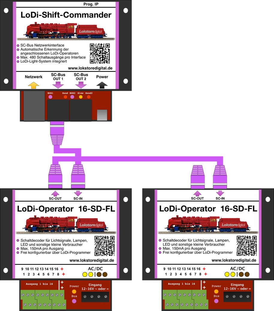
In this example you see how the operators can be chained one after another.
It is important to take care to connect the network cables correctly. That is, from In to Out, as you can see in the picture.
The last example picture shows SC bus 1 and 2 taken to their limits. The order of the modules is entirely irrelevant here.
Only with the LoDi-Light-Controller should you take care that it is connected to bus 2.
It is important to add a new LoDi-SC-Booster to the system after every 16th module.
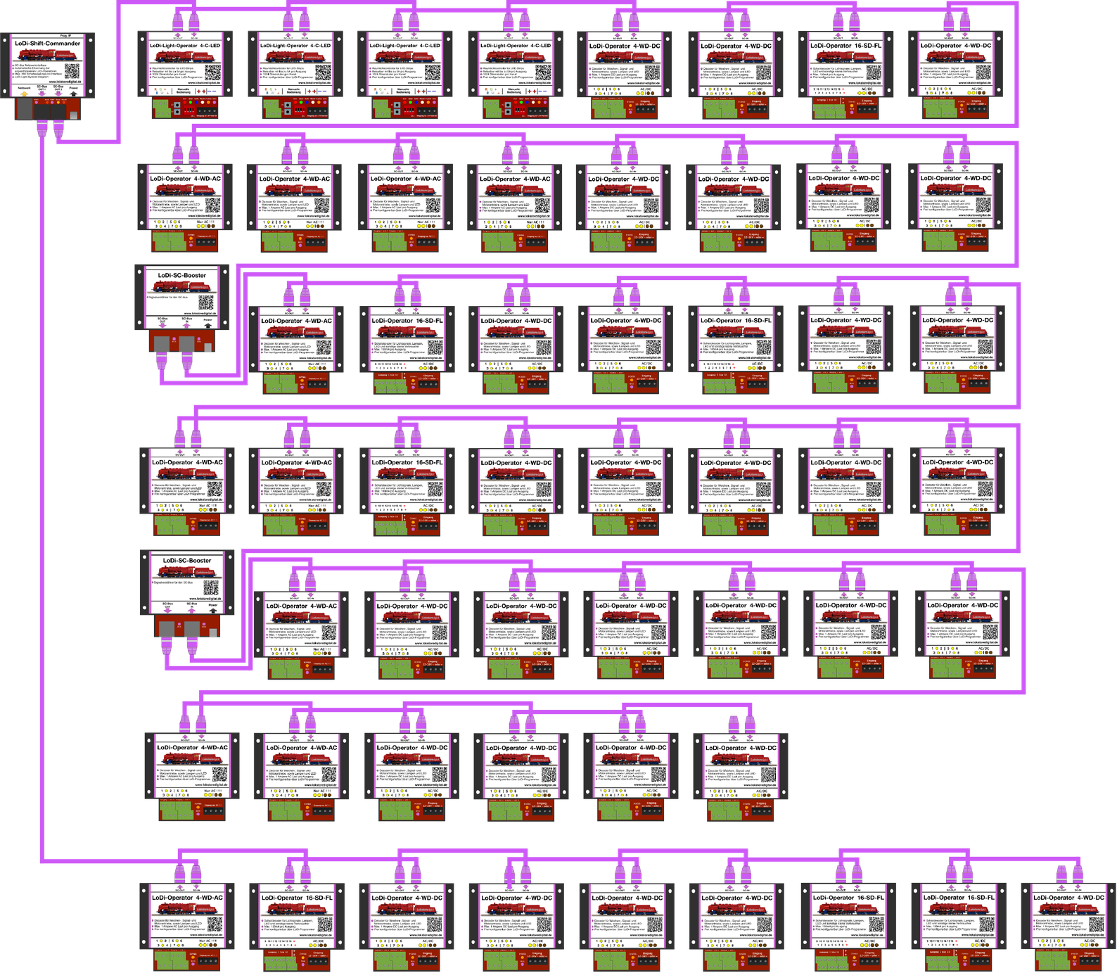
The bus length, or rather the number of modules, is very easy to calculate.
On bus 1 you have 96 channels available.
Here you could connect 12 LoDi-Operators 4-WD-DC or AC, for instance, since each module needs 8 channels.
On the slow bus you have 384 channels available. That would be 48 LoDi-Operator 4-WD-AC or DC units, LoDi-Light-Controller 4-C-LED or LoDi-Operator 16-SD-FL units.
As you can see, our system lets you work very flexibly.
4. Connecting the LoDi-Operator 16-SD-FL (1k) to a model railway transformer
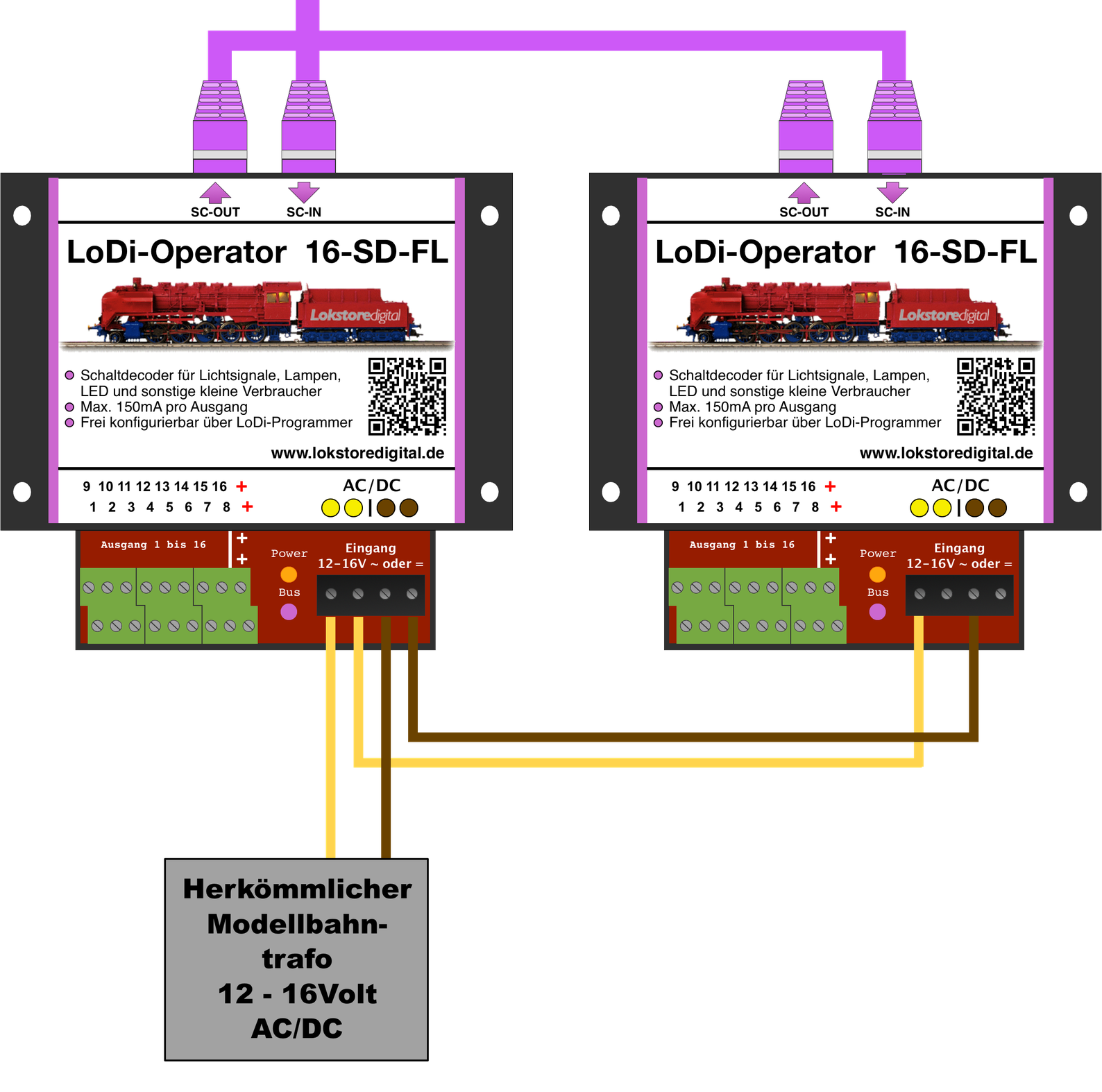
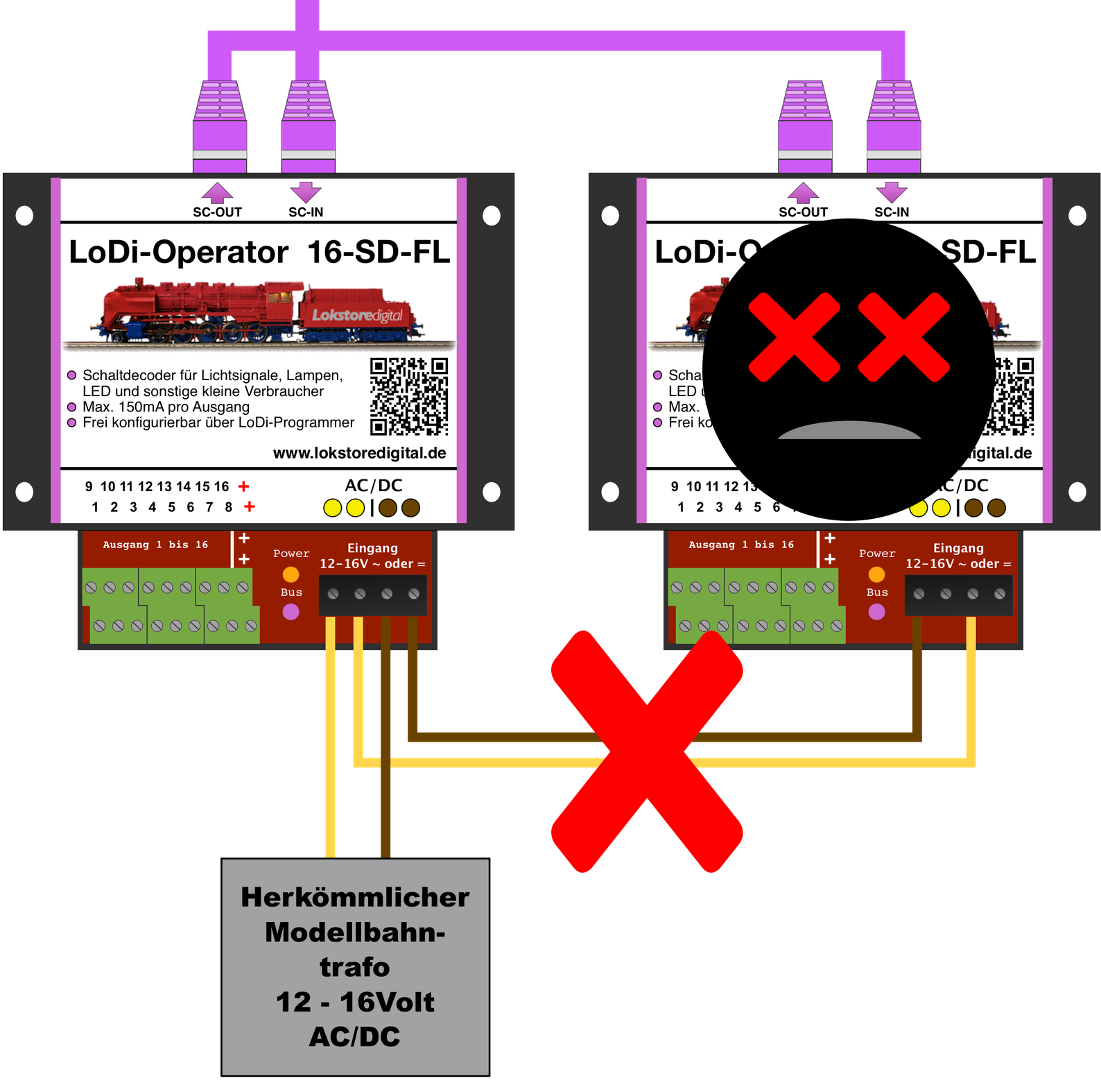
The LoDi-Operator 16-SD-FL (1k) has 4 terminals.
Both do not have to be connected to the transformer; they serve to pass the power on.
You can start the cable at one decoder and keep passing it on to the next.
After 15 decoders a new power feed should be provided.
This makes wiring the system easier.
CAREFUL: do not choose cable below 0.75 mm².
Please watch the polarity of the power supply!
5. Connecting the LoDi-Operator 16-SD-FL (1k) to loads
The LoDi-Operator 16-SD-FL has sixteen channels, each of which can be loaded with 150 mA.
LEDs with a series resistor, lamps, small motors (including the MP1), solenoids and much more can be run on it.
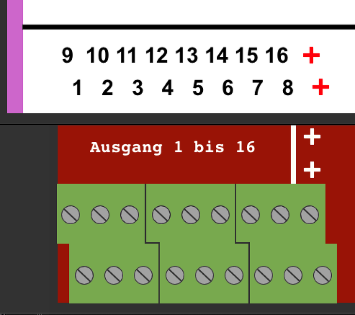
On the LoDi-Operator 16-SD-FL (1k) you will find 18 screw terminals.
Channels 1–16, plus two marked with a +. The plus is the shared return for the 16 channels.
This means every connected lamp or load also has to be connected to that shared return.
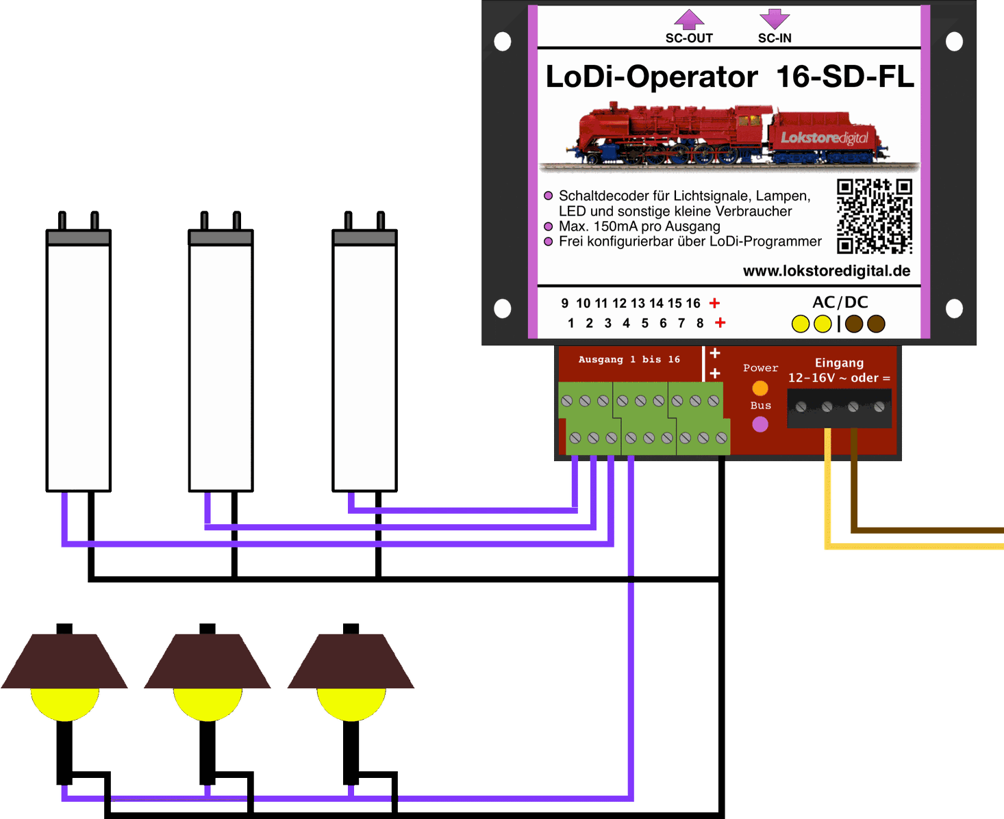
Let us look at a simple example. For switching we use 0.25 mm² cable, with black for the shared return and purple for switching the channels.
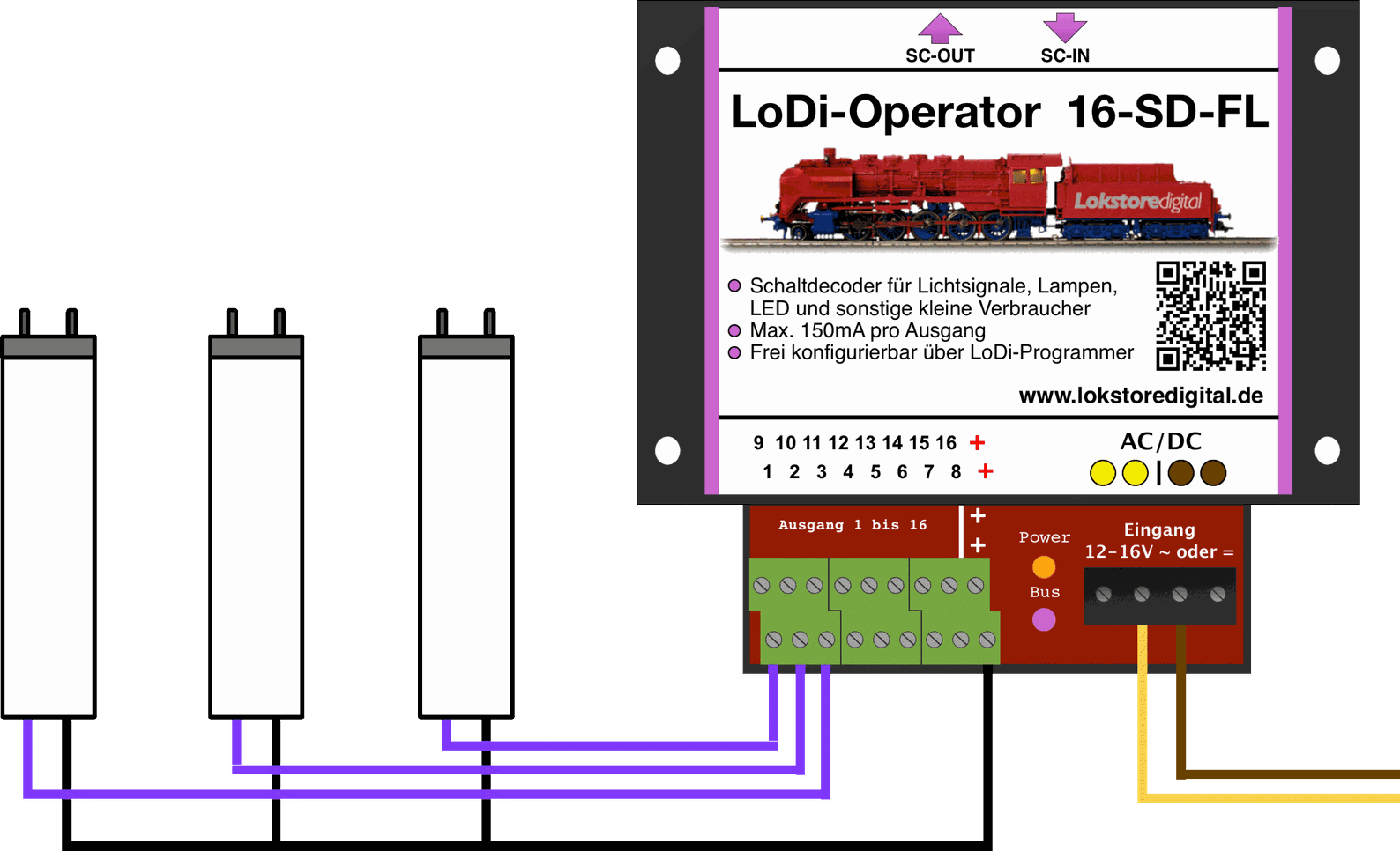
In this example you can see 3 lamps, all connected separately to the decoder. These could be street lamps, for instance, perhaps fitted with a neon effect and meant to be switched on one after another.
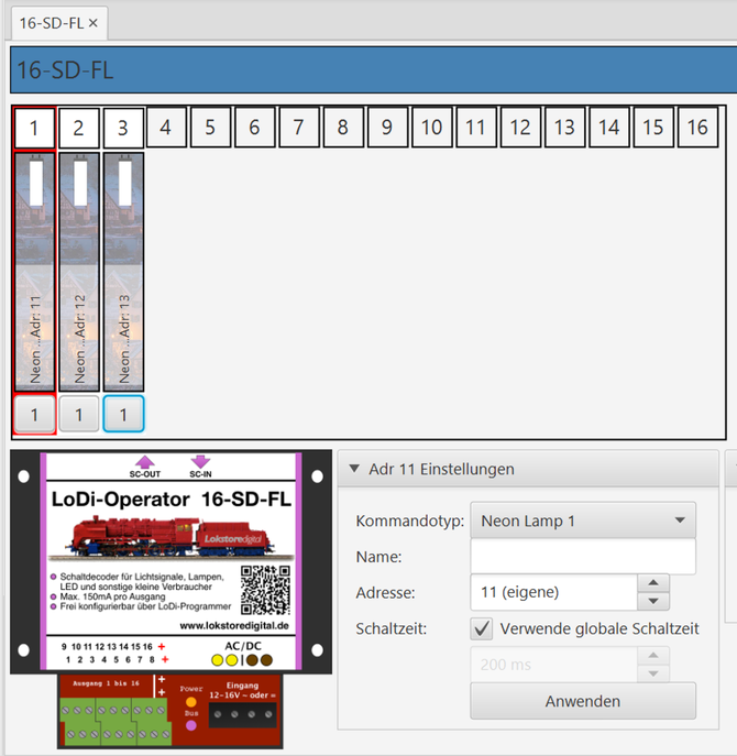
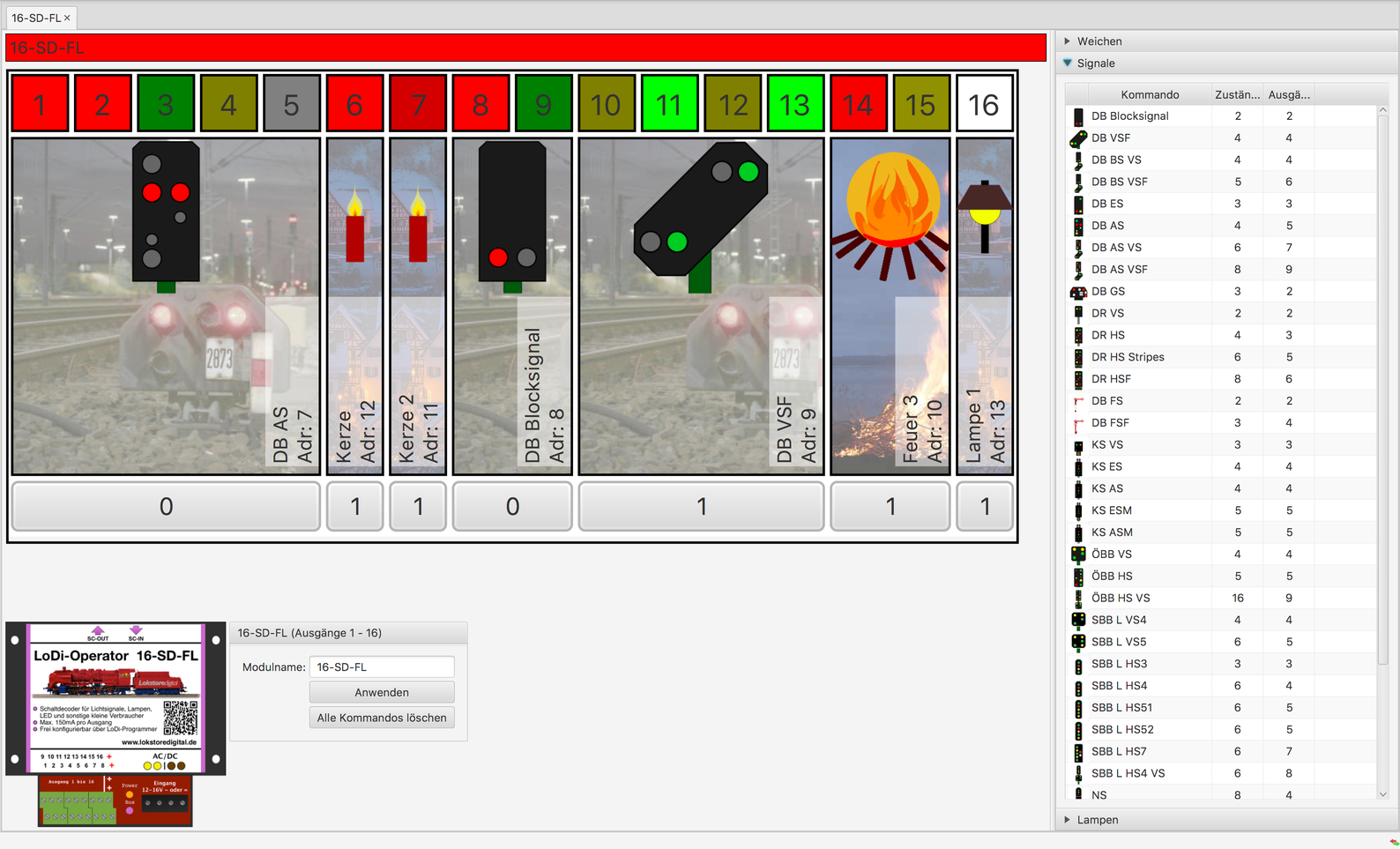
In the LoDi-ProgrammerFX the 16 channels are shown continuously.
In the decoder the first 3 channels are taken up by lamps; these are now placed in the first 3 channels in the Programmer as well.
As the next step we install another 3 lamps, but all 3 of them are now installed on a single channel. Those lamps will then all light up together.
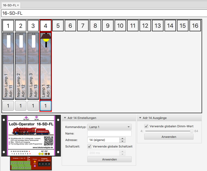
In the LoDi-ProgrammerFX an ordinary dimmable lamp is now configured on channel 4.
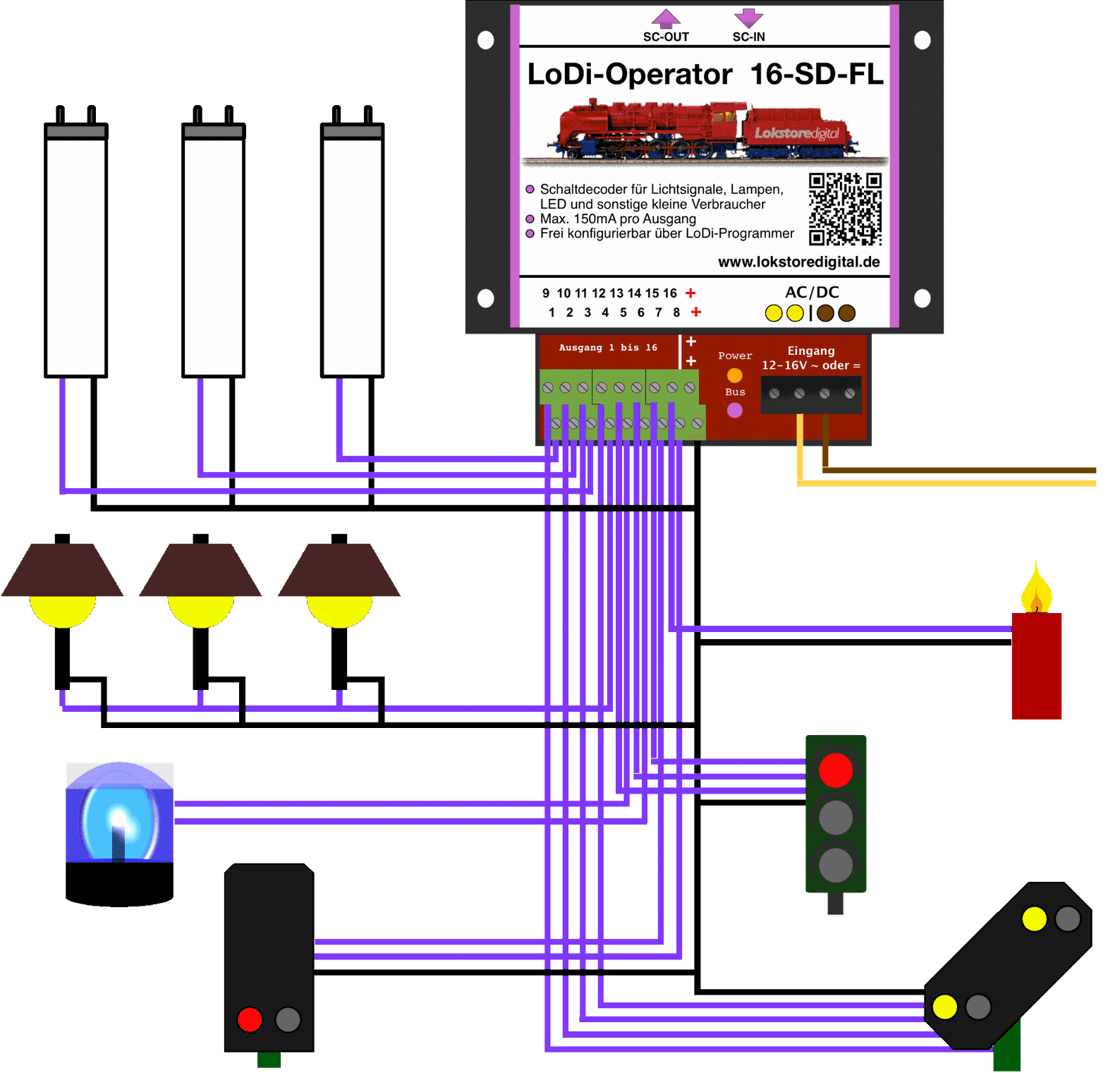
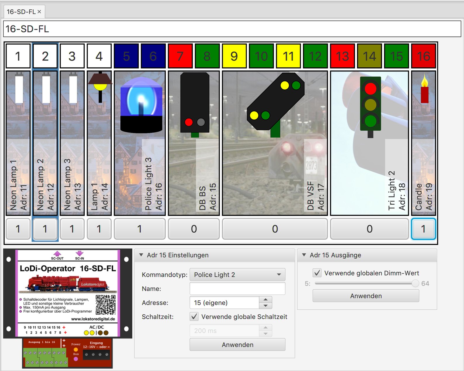
Finally you see a fully configured LoDi-Operator 16-SD-FL. Various loads are now connected to it. Whether a signal, a traffic light or several lamps, the connections can all be configured entirely freely.
6. The LoDi-Operator 16-SD-FL 1k
The LoDi-Operator 16-SD-FL 1k already has a 1 kilohm resistor built into each output.
That means you can connect LEDs and micro bulbs directly to the decoder without a series resistor.
On both side panels of the decoder there is a sticker reading "1K Integriert" (1k built in)
7. Technical data
| Property | Value |
|---|---|
| Dimensions | Length 8.9 cm |
| Width | 10 cm |
| Height | 3.5 cm |
| Weight | 95 grams |
Permissible from 12 to 24 volts DC or AC.
Loadable by loads with 150 mA per output.
The supply voltage can be passed on to the next decoder through the AC/DC terminal on the decoder. The current may be 10 amperes at most.
8. Setting up the LoDi-Operator 16-SD-FL in the LoDi-Programmer
Here you can find out how to set up the LoDi-Operator 16-SD-FL