
Hardware
LoDi-Booster 10A+
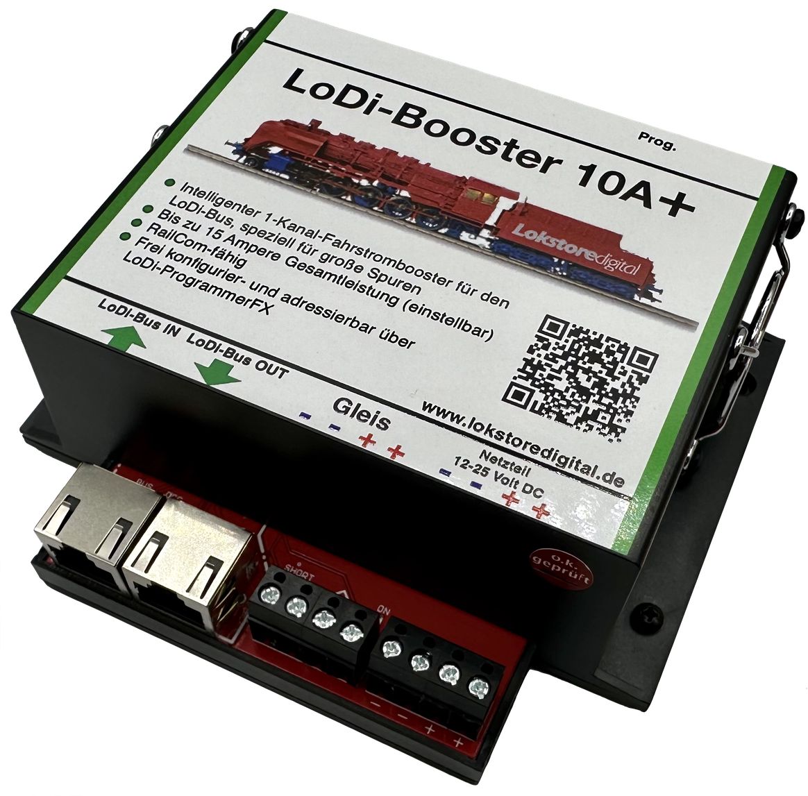
When it has to be more still...
Depending on how large your layout is, enough current has to be provided. Not only that — ideally you should also have some short-circuit logic, so that a single short does not take the whole layout down.
We have many years of experience with these amplifiers in small layouts, large layouts and show layouts, and can now present our LoDi-Booster 10A+. The booster for every scale from 0 upwards.
A perfect fit for garden railways!
A powerhouse delivering up to 14.99 amperes of output current!
Features of the LoDi-Booster 10+
- It supplies the current needed to run the digitally controlled locomotives and the turnouts, as well as every other consumer on the layout.
- In the event of a short circuit on the layout (caused by a derailed coach or locomotive, for instance) the booster cuts the power to the layout to prevent further damage to the rails or the rolling stock.
- Thanks to the built-in intelligence of the LoDi-Booster 10A+, only the affected sections are switched off in the event of a short, and this is reported back to the control software in use. The rest of the layout can keep running without risk of damage to the rolling stock.
- The LoDi-Booster 10A+ has one output channel with a double screw terminal for easy wiring. (If you need more, you have to connect a corresponding number of further LoDi-Booster 10A+ units to secure the supply.)
- On layouts monitored with RailCom, the LoDi-Booster provides the RailCom cutout, which carries the RailCom return channel.
- The maximum current is easy to set. Does your power supply only deliver 8 amperes? No problem — simply set that in our LoDi-ProgrammerFX or directly on the LoDi-Con.
- Straightforward configuration through the LoDi-ProgrammerFX.
1. The LoDi-Booster 10A+ and its connections
Like its smaller brothers, the LoDi-Booster 10A+ works with the LoDi bus (formerly µCon bus). The LoDi-Rektor is needed as the booster command station.
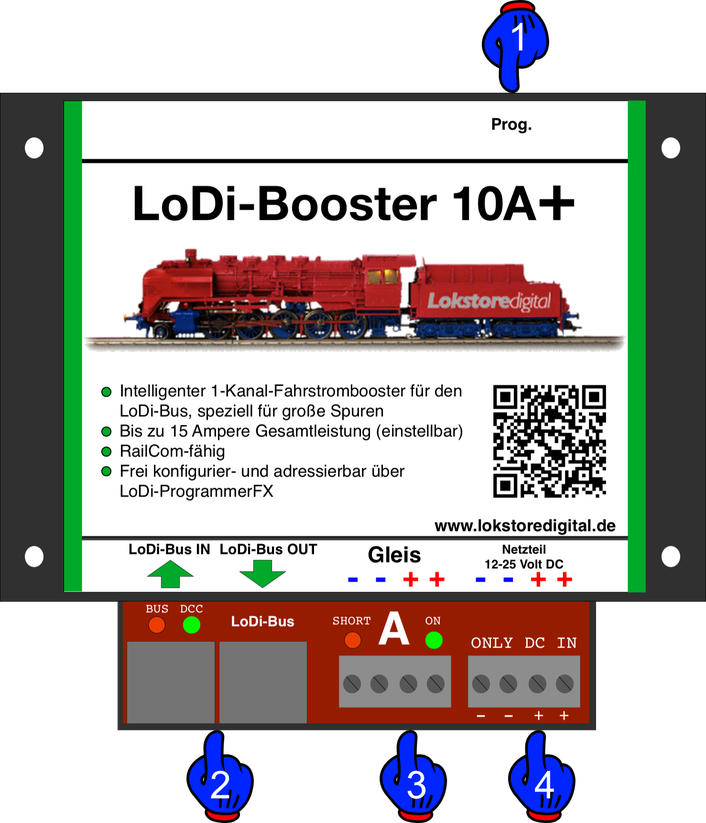
The booster has the following connections:
- (1) Programming button: every booster has its own address through which it is addressed on the bus. To set a new address the button has to be pressed first. The address is then assigned through the commissioning software LoDi-ProgrammerFX.
- (2,3) LoDi bus input: the µCon bus is fed into this socket. LoDi bus OUT: further LoDi bus components connect here. The output also supplies power for other bus devices such as the LoDi-CV-Programmer and the LoDi-TrainSpeed.
- (4) Track output A: the track output can carry 14.99 amperes continuously.
- (5) Power supply connection: (please use only high-quality power supplies! Lokstoredigital accepts no liability for damage caused by inferior power supplies, and the warranty is void in that case.)
2. LEDs and programming button of the LoDi-Booster 10A+
The LED indicators on the LoDi-Booster 10A+ give you information that helps with troubleshooting and with setting the device up.
- (2) BUS LED = shows the state of the LoDi bus. When the bus signal is detected, the LED lights with a short pulsing interruption.
- (2) DCC LED = this LED is lit continuously as soon as the booster receives a signal over the bus — DCC, Motorola or M3 alike. If no bus cable is plugged in, or the µCon-Manager or the LoDi command station is switched off, the DCC LED flashes rapidly.
- (3) Short on track A = this LED indicates a short circuit at the booster output. As soon as a short is detected, the LED starts to flash.
- (3) On for track A = as soon as this LED is lit at the output, the output stage in the booster is active, meaning power is present at that output.
- (1) Prog. button = there is a prog. button on the booster. It switches the booster, or rather its output stages, on and off.
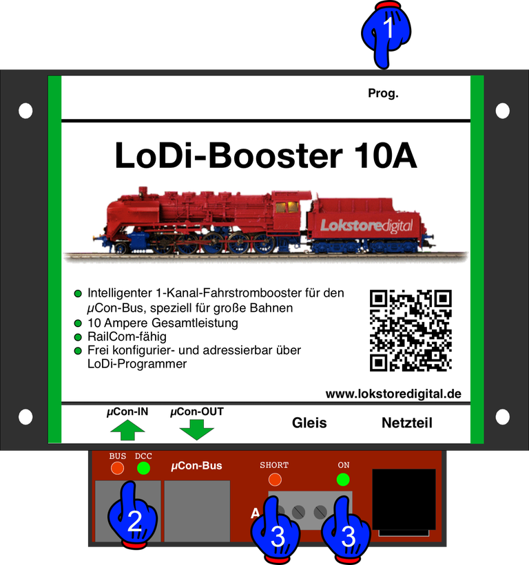
A short tap of the button switches the track outputs off and on again. The ON LED for track A goes out or lights up accordingly.
The prog. button is also used to programme the address. The LoDi bus provides 63 addresses. Held for more than 3 seconds, the bus and DCC LEDs flash red and green alternately. This can be interrupted by pressing the button again, or it ends when a new address is sent to the LoDi-Booster 10A+ over the µCon bus. Once the LoDi-Booster 10A+ understands the signal, programming ends and it returns to normal operation.
3. The fan on the LoDi-Booster 10A+
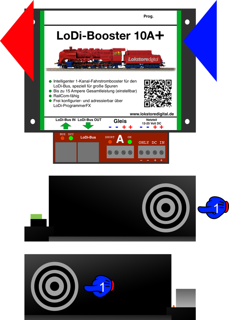
The LoDi-Booster 10A+ has a built-in fan. This fan is controlled by temperature and load. As soon as the temperature inside the device rises, or current is drawn at the output, the fan automatically speeds up and slows down.
The fan never stops entirely; it keeps turning at low speed even when idle.
Please make sure that no objects get inside the device through the slots. Screws and the like could cause an internal short circuit and destroy the device.
The ventilation grille protects against the spinning fan.
The booster should be mounted so that the warm air can flow through it. Allow enough space for the air coming in and going out; 5 cm of clearance on each side is enough.
The air is pushed through the device from right to left.
4. Connecting a power supply
The LoDi-Booster 10A+ is delivered WITHOUT a power supply.
Power supplies with the following ratings can be used: 12–24 volts DC at 8–20 amperes.
Take care to use a high-quality power supply such as Meanwell or another branded unit.
Please do not use power supplies of unclear origin.
IMPORTANT! Please check whether the power supply you are using bonds the earth conductor to the negative output. If it does, that power supply must not be used, as it could otherwise lead to ground loops.
Improper use of power supplies can damage the electronics.
5. Connecting to the LoDi bus
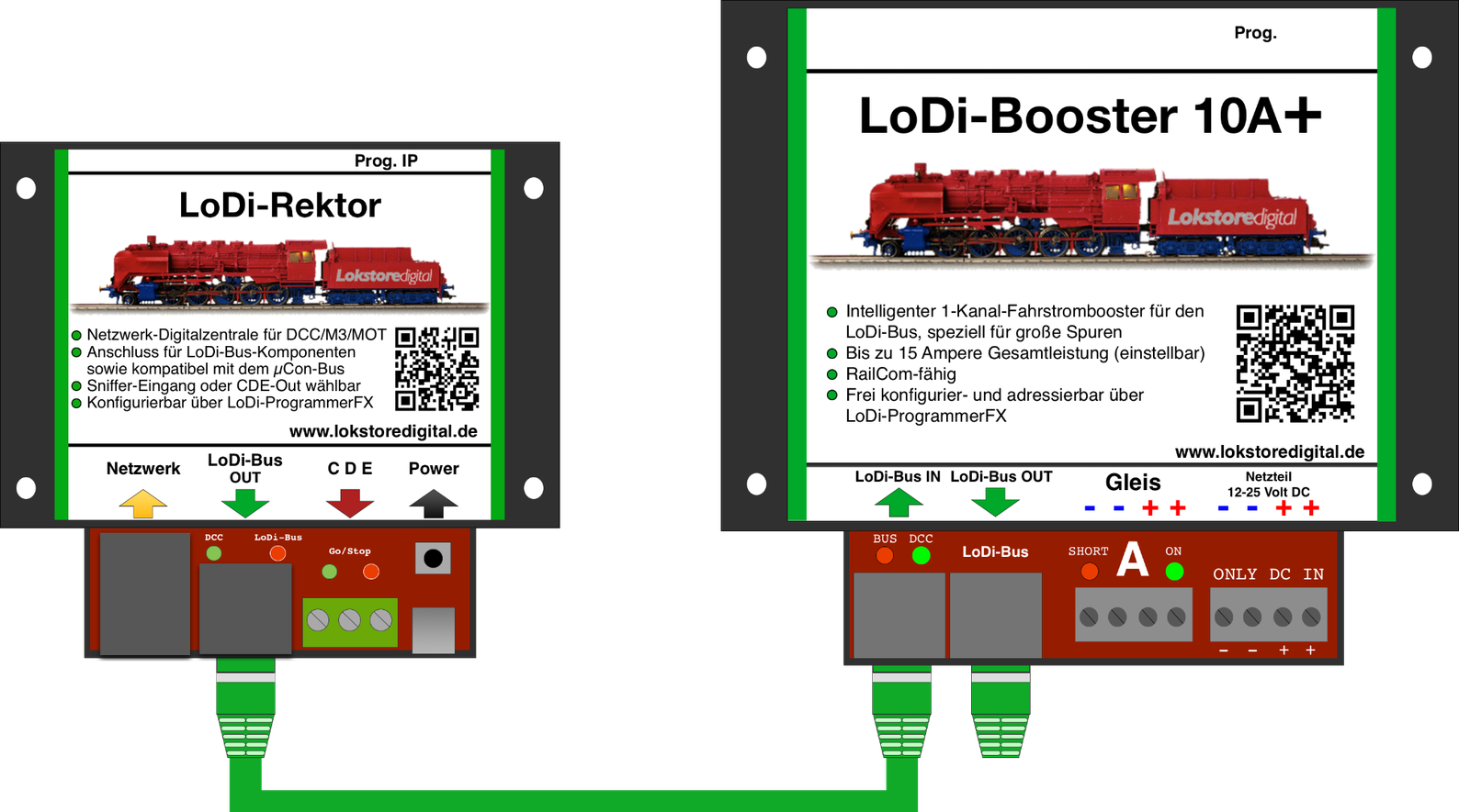
The LoDi bus is a bus developed specifically to cover long distances without losing the data signal. You can connect 63 LoDi bus components in total to the LoDi-Rektor.
Devices on the LoDi bus have to be plugged in one after another; the bus does not allow for a star topology.
The following example shows how the booster is supplied with information by the LoDi-Rektor.
In this case the LoDi-Rektor provides the data for the booster and sends it over the LoDi bus.
Beyond that, the LoDi-Booster 10A+ can also deliver data to the LoDi-Rektor and thus to the LoDi-ProgrammerFX.
That data can include current measurement per channel, voltage measurement, short on A, and device temperatures.
Besides the various short-circuit sensitivities, the address can also be set on the booster through the LoDi-Rektor with the LoDi-ProgrammerFX.
The RailCom cutout can be switched off on the LoDi-Booster. You will find more on that in the LoDi-ProgrammerFX section.
The LoDi bus can manage 63 devices in total, and the patch cables may run to more than 1500 metres. On garden railways in particular that makes it very neat to create individual booster stations.
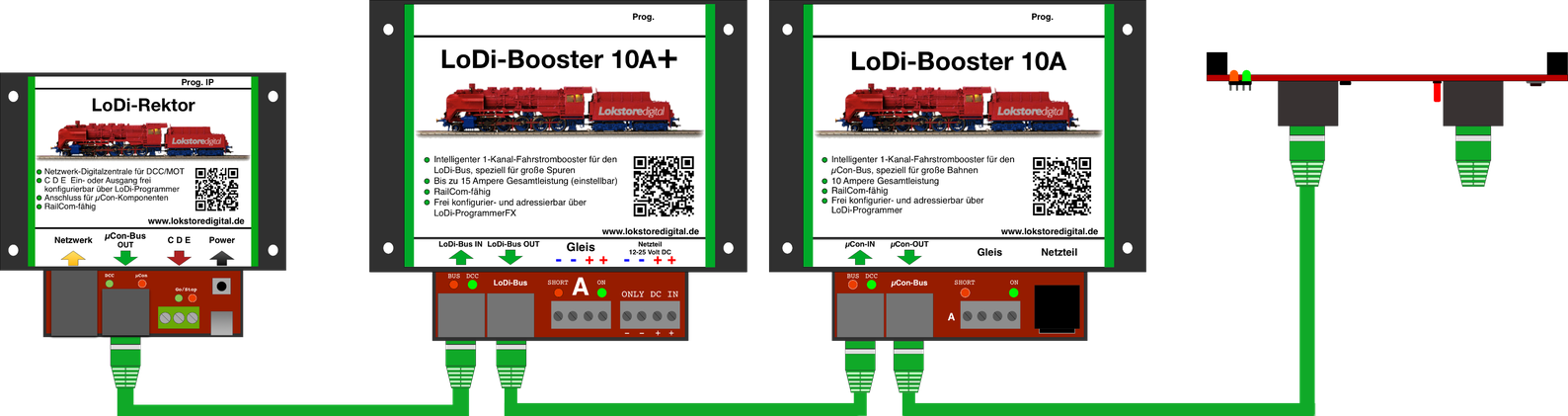
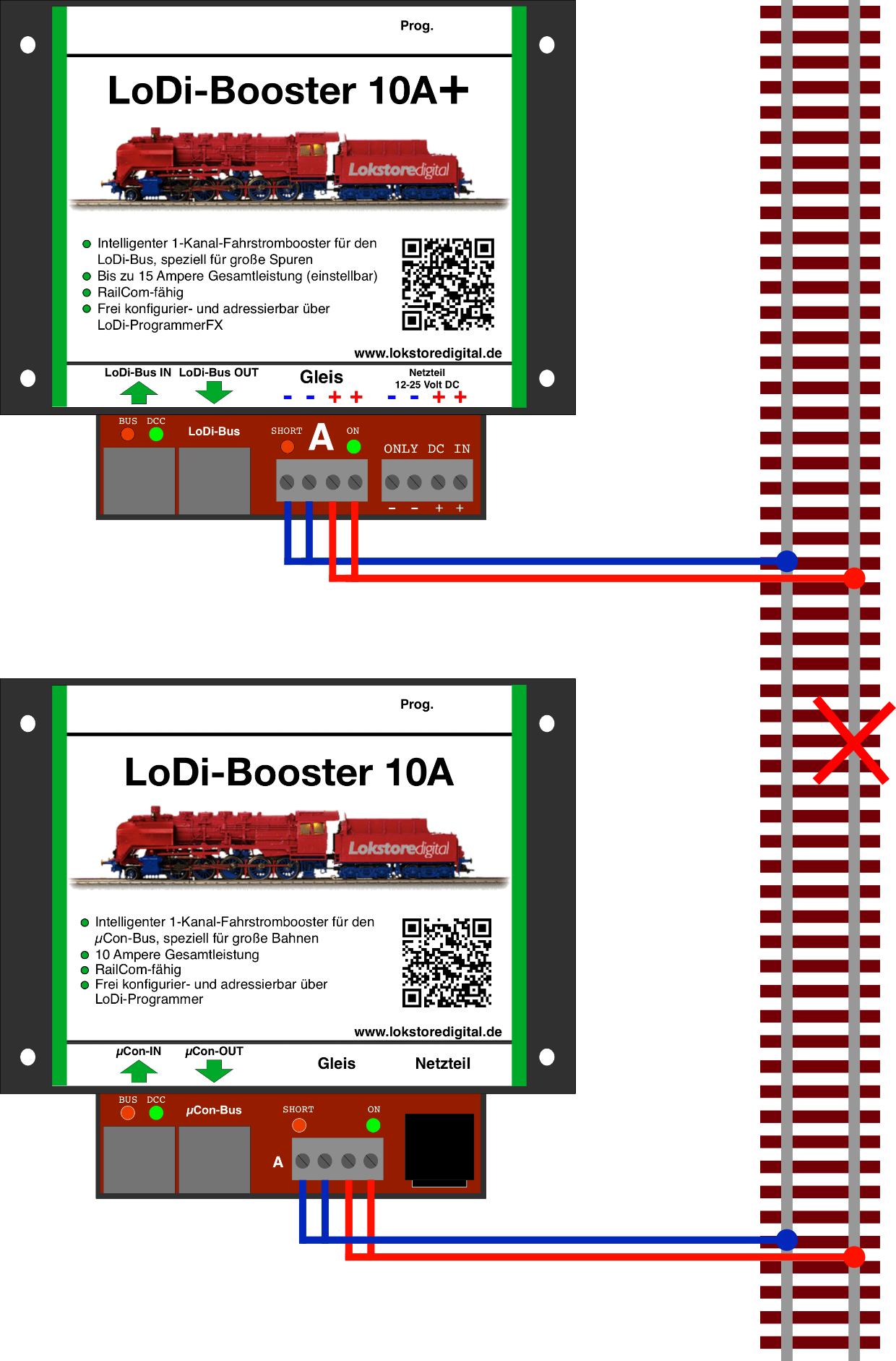
The LoDi-Booster can also be hung on the bus, where it can supply the current for switching turnouts, for instance. Important note: the LoDi-Booster and the LoDi-Booster 10A+ must not be run mixed together. The high output of the LoDi-Booster 10A+ could damage the smaller LoDi-Booster.
The LoDi-Booster 10A and the LoDi-Booster 10A+, on the other hand, can be used together in one system without trouble.
6. Connecting to the track
20 amperes is of course a great deal of power. With the 20 ampere version in particular, sufficient cable cross-section is therefore essential. We recommend never going below 0.75 mm².
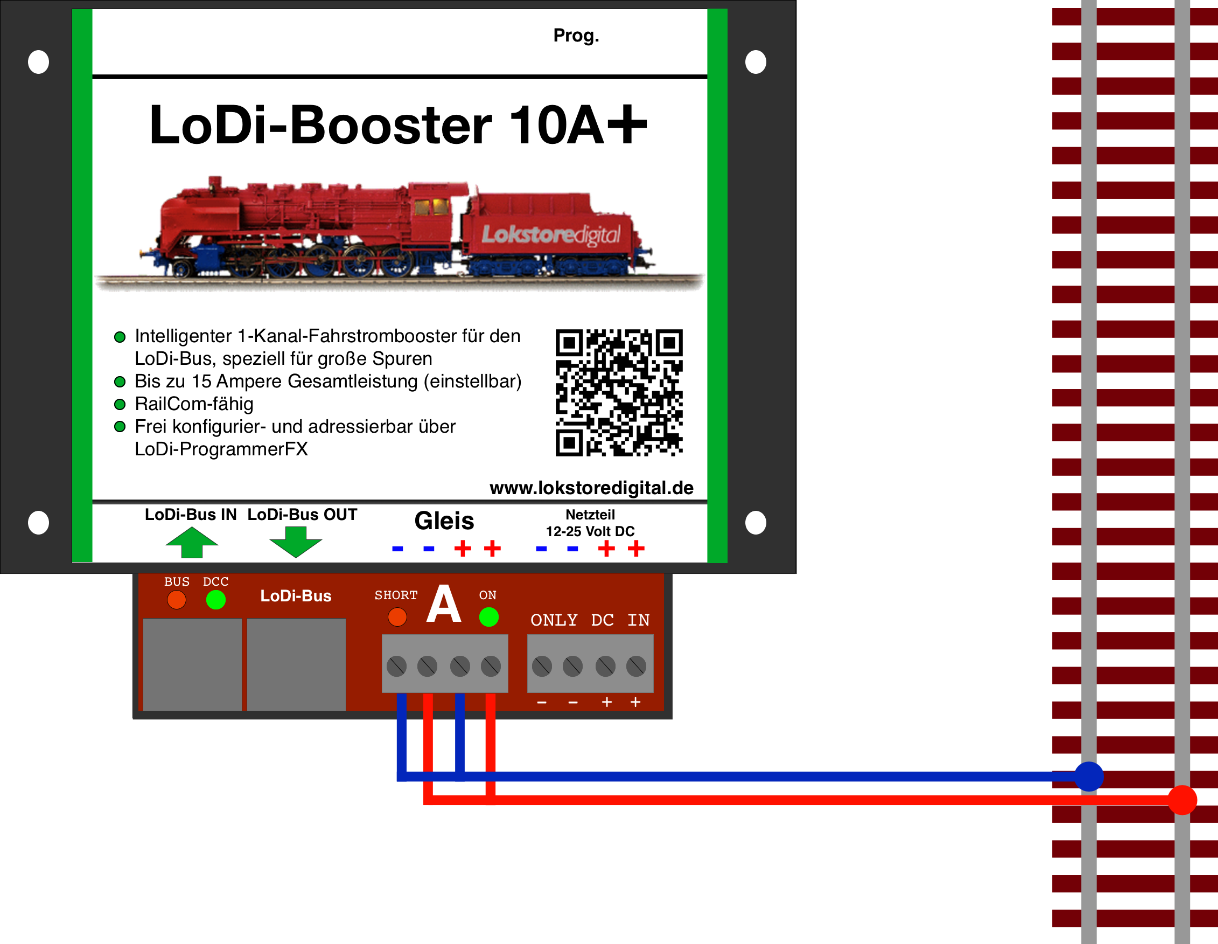
On the LoDi-Booster 10A+ we use a double terminal. It carries the common twice on the left and the positive conductor twice on the right.
With the LoDi-Booster 10A and 10A+ the commons may be joined through the track.
7. Connecting to the track through feedback modules
The LoDi-Booster 10A+ is an excellent match for feedback modules that are RailCom capable. In this example we take the LoDi-8-GBM-P, a RailCom capable feedback module that can carry 10 amperes per channel.
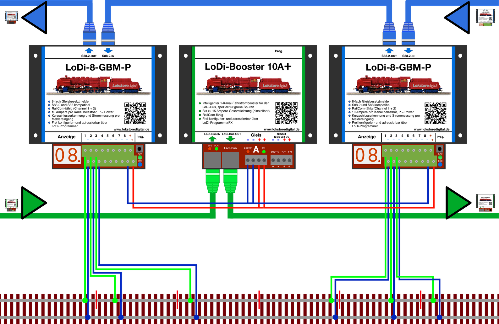
The diagram shown here has two feedback modules, each connected to one of the booster's double outputs. The cable cross-section should not be below 0.75 mm². There is no separation of the common here; that is not important with the LoDi system, but it can be done if you wish.
Please note that you need feedback modules that can take the booster's load. In this case the module has to carry 10 amperes per channel.
How many feedback modules you need depends entirely on your layout and on the software you work with. If you need help here, do get in touch with us or with our service partners.
8. Dividing the layout into booster sections
With the intelligent booster system we bring logic to the track, so that a short circuit does not bring the whole layout to a stand. The data is passed to the control software, which then knows where the short happened and holds trains before they enter other booster areas that are shorted or switched off. For that you naturally have to divide up your layout, or rather the track plan. One booster output is available per device. That means you can secure very good logic and operating sequences with only a few units. Here is a small example of a division.
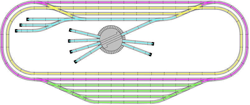
In this example we use four LoDi-Boosters, which gives us four power sections. The different circuits are colour-coded. If a short is now detected in one of these areas, that is passed to the LoDi-Rektor, which forwards the affected track section to the control software. The rest of the layout keeps running where possible.
9. Technical data
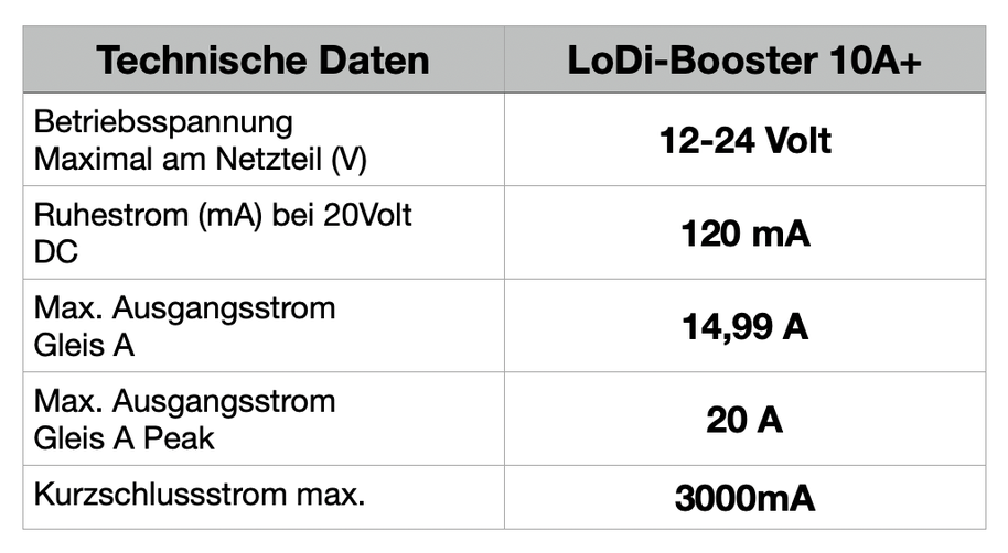
The LoDi-Booster 10A+ has a total output of 14.99 amperes.
It has thermal overload and temperature protection, which makes sure the LoDi-Booster 10+ takes no damage when overloaded.
Dimensions:
Length: 130 mm
Width: 115 mm
Height: 45 mm
Weight: 225 g
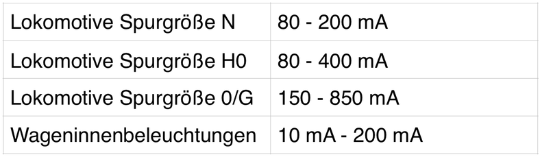
This table gives you a rough estimate of the current draw.
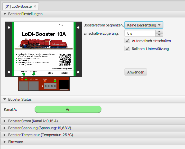
10. Setting up the LoDi-Booster 10A+ in the LoDi-ProgrammerFX
and updating the firmware Here is how to set up the LoDi-Booster
11. LoDi-Booster 10A+ PDF download
Here you can download a summary of the LoDi-Booster 10A hardware and software as a PDF.