
Hardware
ICE 2 with power car or cab car
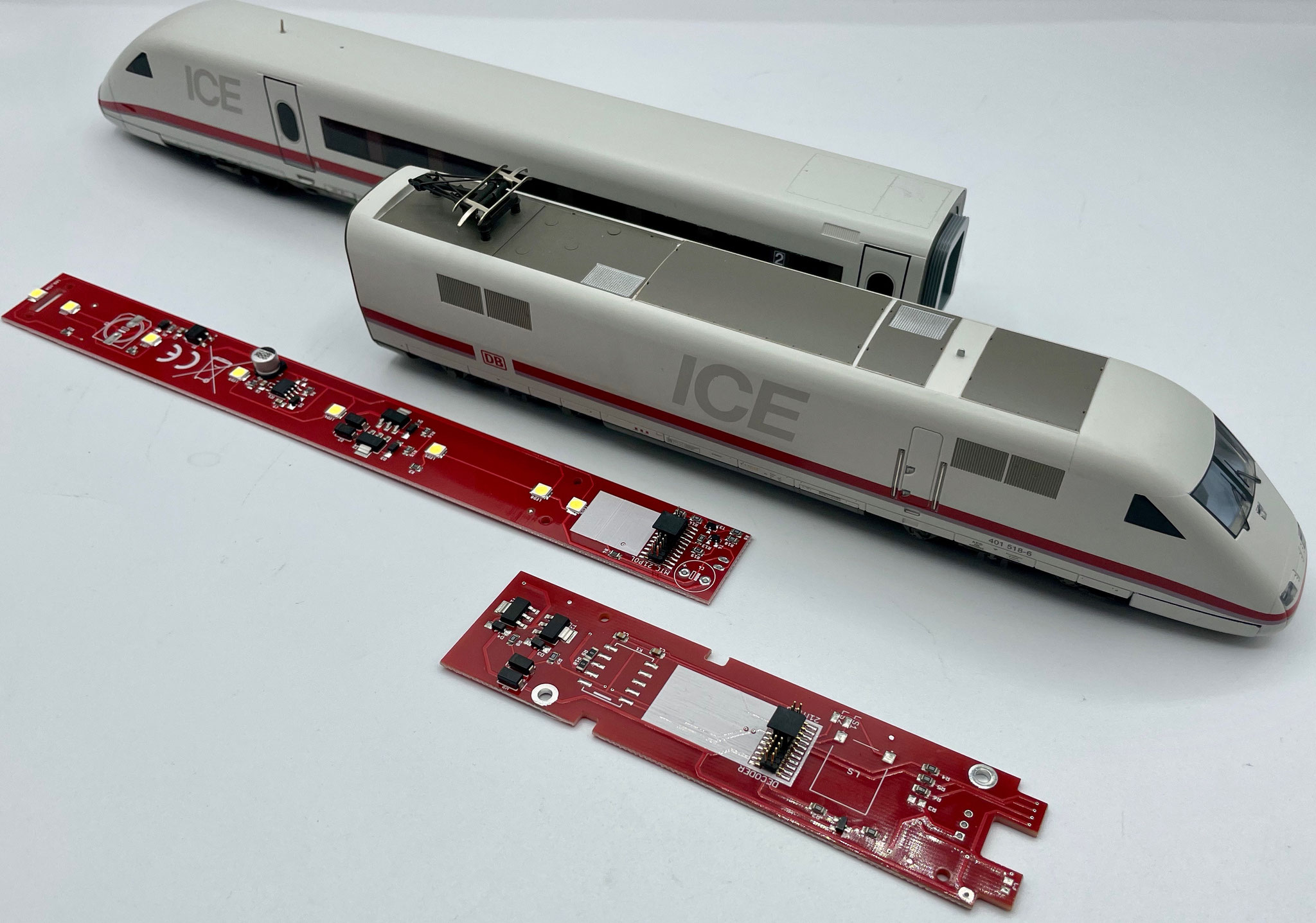
There are several ICE 2 variants: digital and Delta.
In principle all of them can be converted and brought up to modern technology. In this example we want to show you the ICE 2 with 1 motorised car and 1 cab car in a set with 2 coaches.
Converting to our LoDi-Motor WiB ICE-M gives you the following advantages:
- 21-pin MTC interface in the motorised and the unpowered power car
- No earth springs in the coaches at all (which greatly improves how freely the coaches and the whole train roll)
- Absolutely flicker-free thanks to reliable transfer through the current-carrying coupling.
- Speaker preparation right on the board
- Easy to convert
We are often asked whether to go with or without pickup changeover.
Let us explain briefly:
- If you run a computer-controlled layout, in most cases you have no power interruptions at signals. If that is the case you do not need pickup changeover. We connect the pickups front to back, which has the advantage that the train draws current from twice as many points.
- If you still have signals installed that affect the train, you have to use the LoDi-Motor WiB ICE-M-S. There the pickup has to be switched over from the front one to the rear one.
In our current example we do not use pickup changeover.
1. The motorised power car
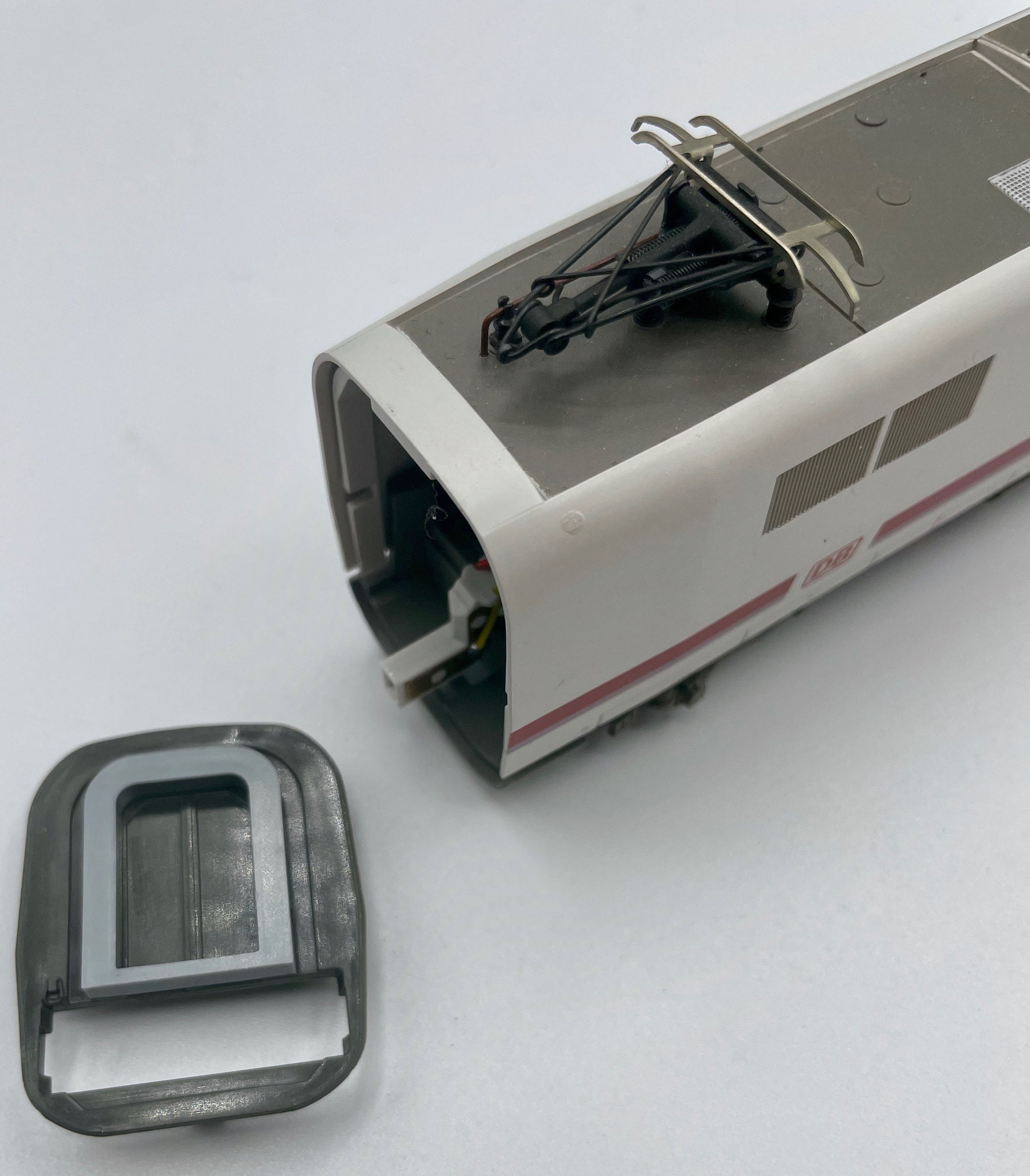
First we pull the cover off the coupling.
On the underside of the power car there is a slotted screw, which also has to be removed. The body of the power car can then simply be lifted off.

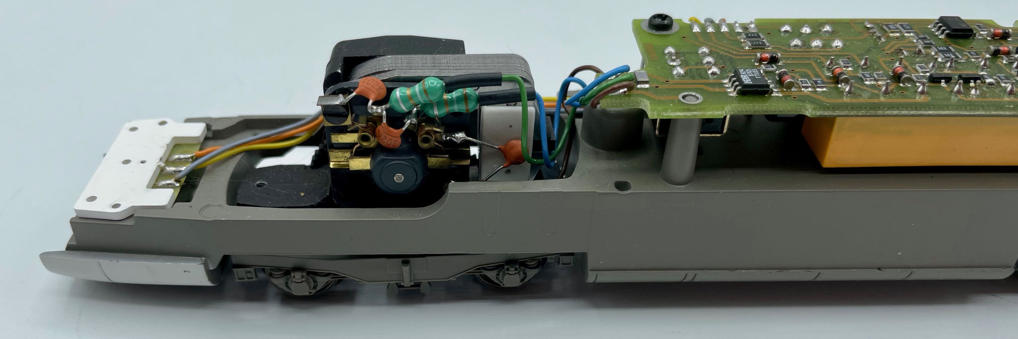
Once you have taken the top off, you should first check the condition of the motor. A 5-pole high-performance motor should be fitted in any case. In most cases it already is.
There are 3 capacitors on the motor in total. Two of them should be removed. Modern decoders do not support them and they otherwise interfere with motor control.
You can now unsolder the old board and take it out of the housing along with the 2 mounting screws.

Now we fit the LoDi-Motor WiB ICE-M and screw it down the same way the original board was.
Now solder the cables from your original train back on as follows: left-hand side
- Pickup = black cable
- RT coupling = red cable
- GE coupling = yellow cable
Right-hand side
- Ground = brown
- Aux 5 = amplified output for cab lighting
- Motor L = green
- Motor R = blue
- VCC = orange
- L_RT = yellow
- L_WS = grey
Careful: on the ICE 2 power car the lighting board may be switched over +, whereas our board switches −. We will shortly be offering a conversion kit for this.

For our conversion we use an ESU LokPilot V5 MKL. You can use any 21-pin decoder, though — it only needs amplified outputs on F1 to F4. Aux 5 can be a logic output.
Here is the breakdown of the functions of the LoDi-Motor WiB ICE-M:
Light front = head light white
Light rear = head light red
Aux 1 = pickup changeover, power car 1
Aux 2 = pickup changeover, power car 2
Aux 3 = high beam (if fitted)
Aux 4 = coach lighting
Aux 5 = cab lighting

From motor board version 1.50 onwards there are 2 solder jumpers. They can be used if you are not using pickup changeover. With these jumpers the interior lighting of the coaches is switched through the coupling. They exist so that the decoder's Aux 1 function output can be used, which means no loco decoder with amplified Aux 3 and Aux 4 is required (without MKL).
If the jumper is set at SJ1, switching happens over Aux 4; at SJ2 it is Aux 1.
CAUTION!!!
Only ever one jumper may be set. If both solder bridges are set, it could destroy the decoder!
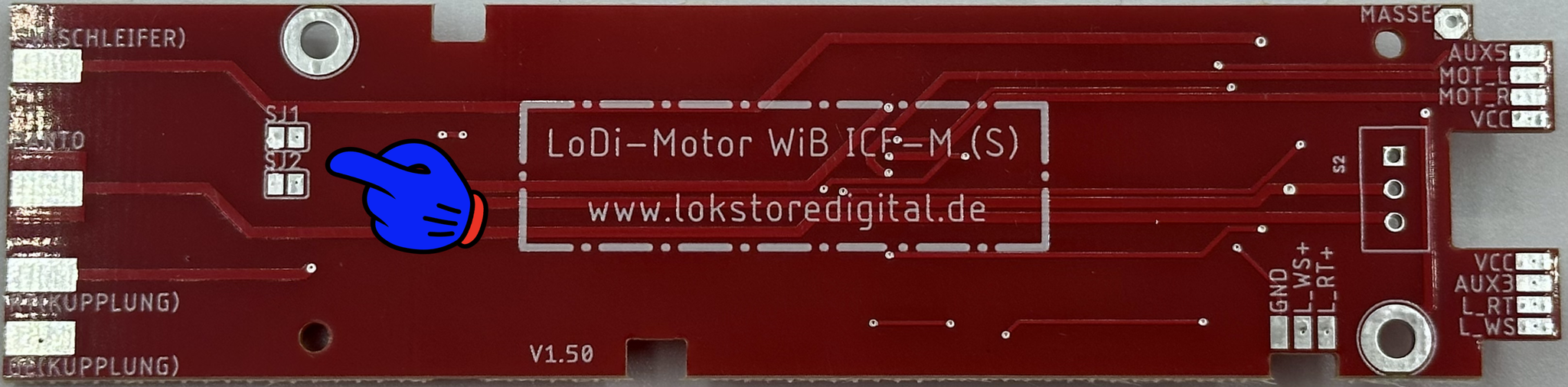

Should you want to fit a sound decoder in one power car or even in both, we have left room for a speaker on the board. You can also connect it to separate solder pads.

2. The unpowered power car
In principle this train also runs excellently with 2 motors — that lets us pull train lengths of up to 14 coaches. If it is to stay a short train, though, one motor in the whole train is enough in most cases. Nor does the power car without a motor have to be converted. But if you would like to fit front LED lighting here as well, you can use the LoDi-Motor WiB ICE-M here too.
In that case we can do without the pickup changeover (-S).

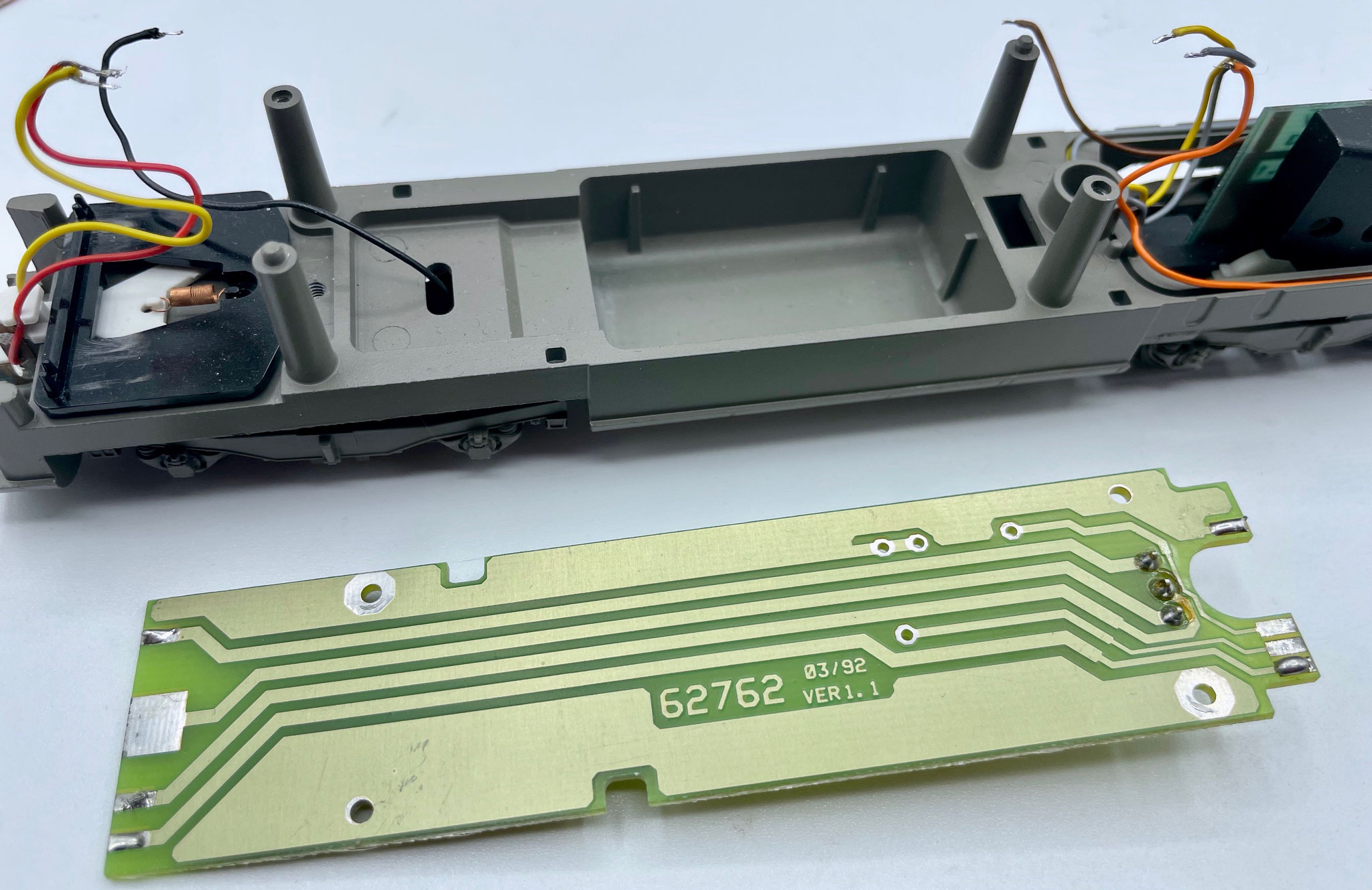
Let us start by opening the power car without a motor: again pull the cover off the coupling and remove the screw on the lower part of the power car.
Now remove the screws of the original board straight away and unsolder the cables.

In our example the power car without a motor is also fitted with the LoDi-WiB-ICE1, so that the head lights are LEDs here as well.
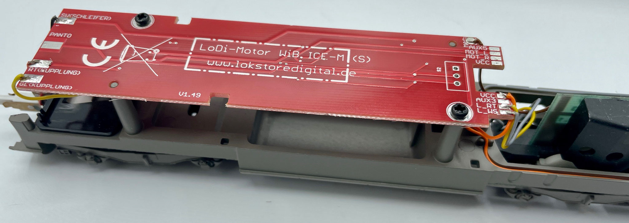
Now screw the LoDi-Motor WiB ICE-M into the power car. Connect the cables as follows:
- Left pickup = black cable
- Left RT coupling = red cable
- Left GE coupling = yellow cable
- Right brown = ground
- Aux 5 = connection for cab lighting
- Orange = VCC
- Grey = L_WS
- Yellow = L_RT
The old changeover for the lighting can be removed; it is no longer needed.

For our conversion we use an ESU LokPilot FX V5. You can use any 21-pin function decoder, though — it only needs amplified outputs on F1 to F4. Aux 5 can be a logic output; we use it to switch the cab lighting and it is amplified on the board.
Here is the breakdown of the functions of the LoDi-Motor WiB ICE-M:
Light front = head light white
Light rear = head light red
Aux 3 = high beam (if fitted)
Aux 4 = coach lighting
Aux 5 = cab lighting
3. The head lights on the ICE 2
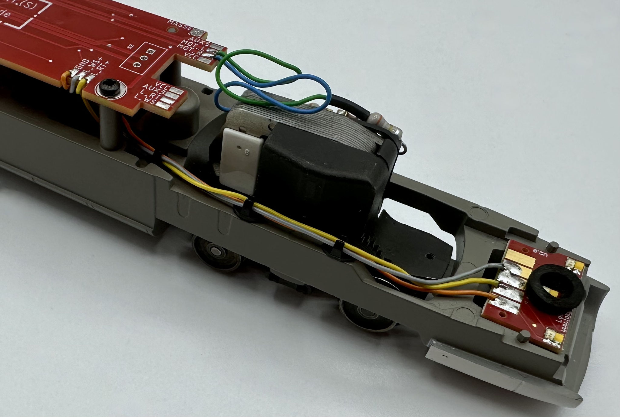
There were a number of different head light assemblies across the various models. That is why we gave the motor board a small update: from motor car board version 1.50 onwards the head lights can also be switched over +. As a rule the LEDs are switched over −.
The LoDi-ICE2 front lighting board is available in two versions, positive or negative switching, which makes it fully compatible with your old decoder should you only want to replace the lighting in the power cars.
The board has insulation around the middle LEDs, which largely prevents the red LEDs from shining through from below. In addition the light guide can be protected against shine-through with black insulating tape on top.
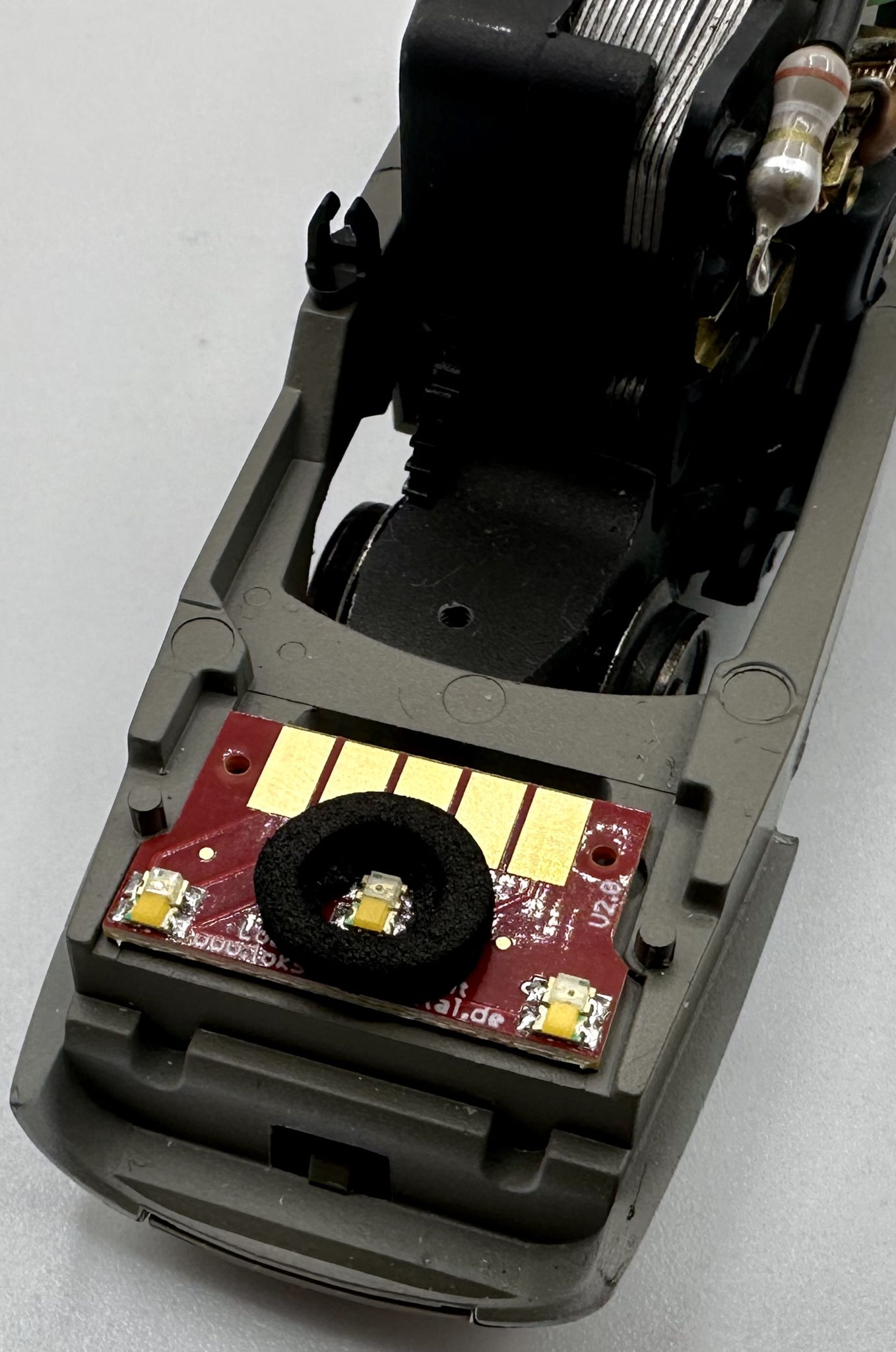
The LoDi-ICE2 Front is fixed with double-sided tape on the back. Simply remove the old board, pull the protective film off the tape and stick the board into your ICE 2. You can also use the board for the cab car — there, however, the positive switching LoDi-ICE2 Front is mandatory.

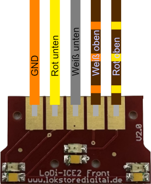
The LoDi-ICE2 Front has 5 solder pads to which the cables can be soldered.
It can switch the upper white LED separately, which would make a high beam at the bottom possible, for example.
It also has an upper red LED, which can be used to simulate a warning light in case of a fault, for instance.
In this first wiring example you see a positive switching LoDi-ICE2 Front. In this diagram the orange cable carries − (that is, GND), while the red and the white cable are switched over +.
The grey cable is connected through pads 3 and 4, so that all white LEDs light when running forwards.
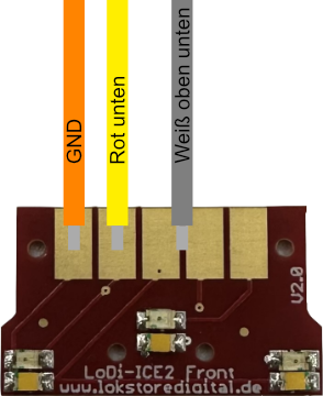

Here is the example for high beam and warning light.
The grey cable now goes only to pad 3, which drives the lower white LEDs. The white LED on pad 4 at the top can now be driven separately over another Aux channel. And over pad 5, again with another AUX channel, the red LED at the top can be programmed in the decoder as a fault light.

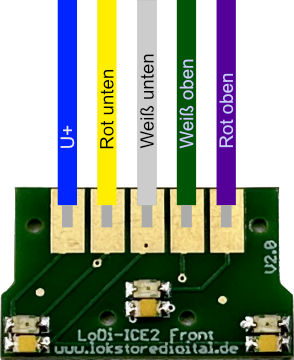
The LoDi-ICE2 Front is also available as a negative switching variant. The positive board is red, the negative one green.
The colours here follow the DCC standard.
Pad 1 U+ = common return
Pad 2 yellow = red, bottom
Pad 3 white = white LED, bottom
Pad 4 green = white LED, top
Pad 5 purple = red LED, top

4. The ICE 2 cab car
There are several ICE 2 train sets with a cab car. Unfortunately the normal LoDi-WiB ICE-M does not fit in them, so we developed a dedicated board for the ICE 2 cab car. It installs just as quickly and easily as the LoDi-WiB ICE-M.
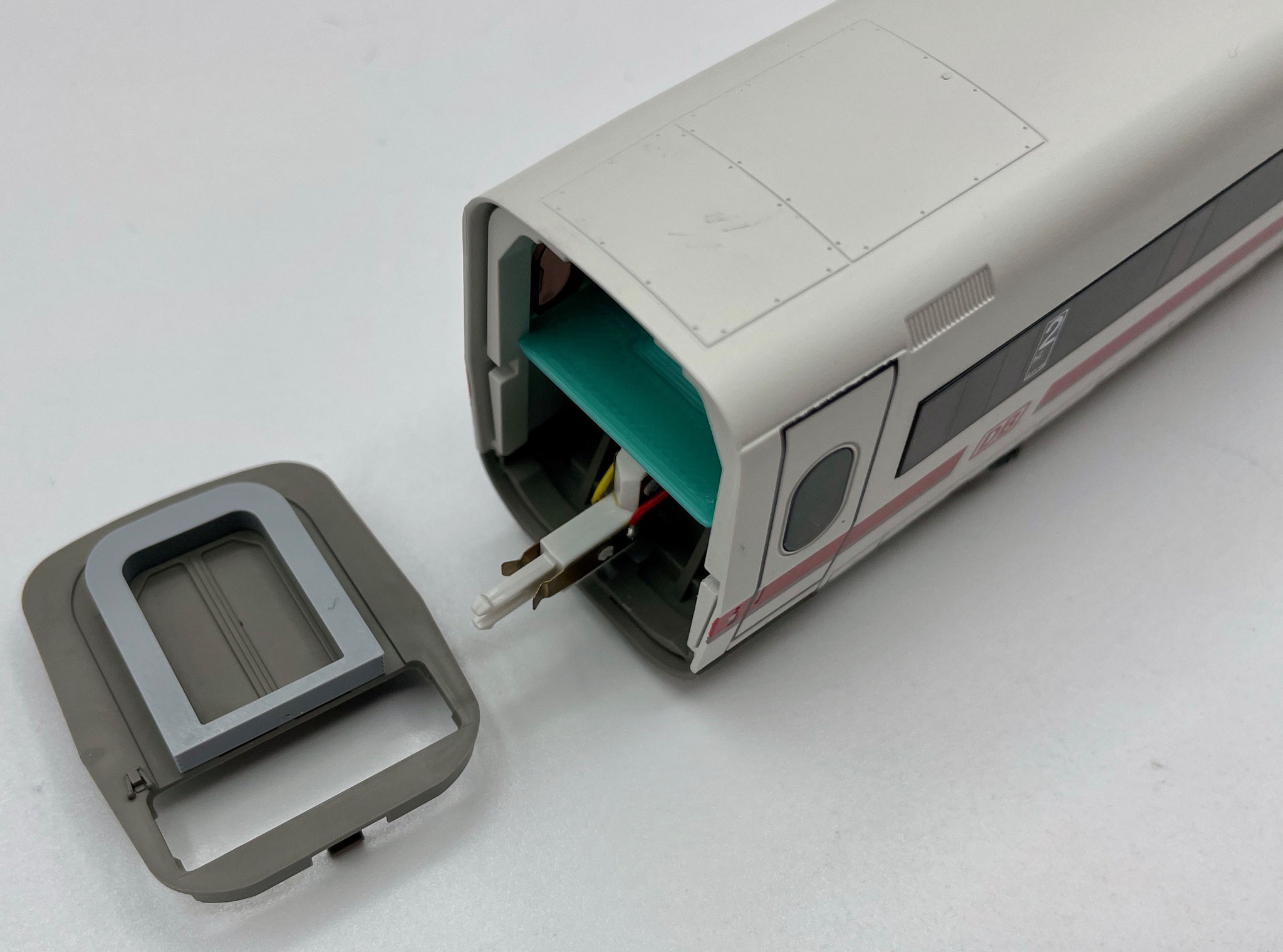
Start by pulling the bellows off the coupling end.
The upper shell of the coach can be eased apart a little and then pulled off, just as with an ordinary compartment coach.
Unsolder the cables from the old board and take it out of the coach.

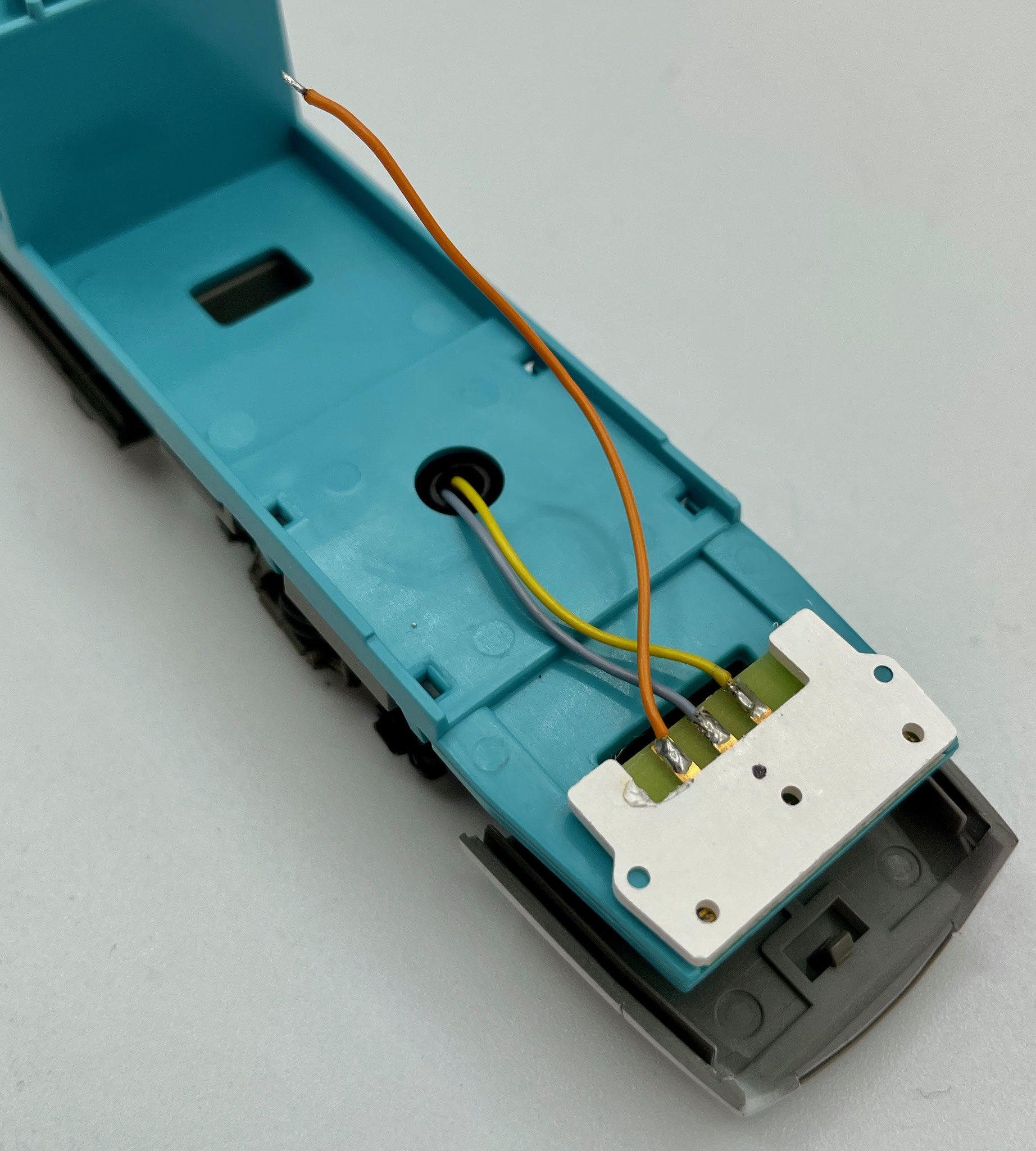
Next we have to adapt the head lighting for the new board: the trailing switch on the wheelset is removed completely, and the two cables that ran downwards and were attached to it are pulled up through.

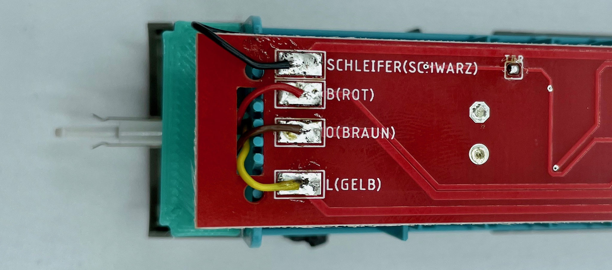
At the coupling end, thread the two cables coming up from the coupling through the hole in the board and solder them on according to the labelling.
Then solder the lighting cables on the front end to the board according to the labelling as well.

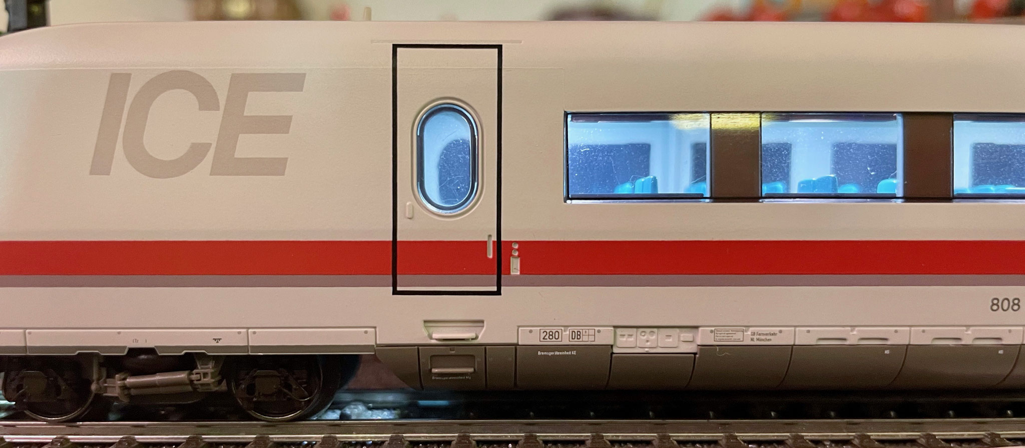
We built door and gangway lighting into the LoDi-WiB ICE2 St, but it has to be activated with a solder bridge. You will find the solder bridge on the coupling side, marked with the green arrow in the picture.


A buffer capacitor can optionally be fitted to the LoDi-WiB ICE2 St. There are 2 ways to connect it: C2 as SMD or wired, and C4 wired.
Electrolytic capacitors from 25 volts and 220 µF upwards can be used.

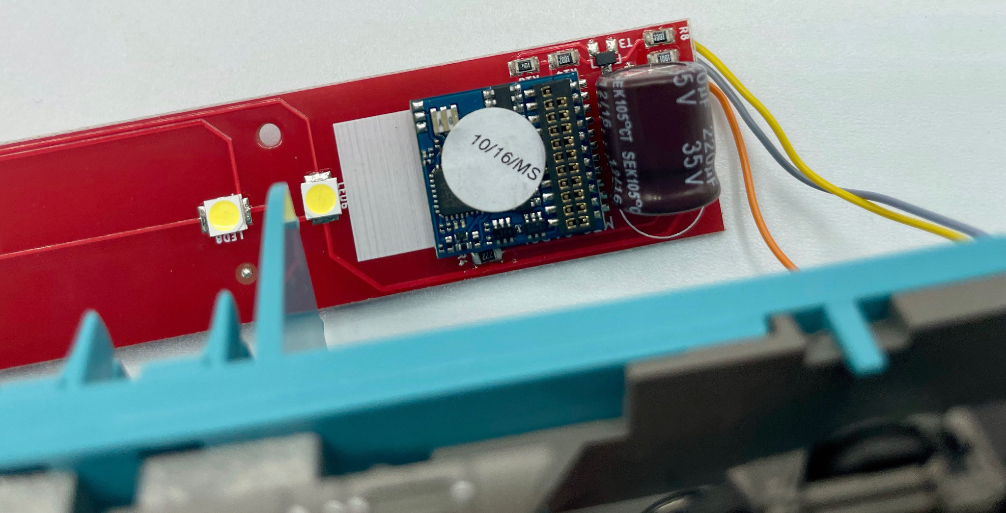
Now plug the function decoder of your choice onto the 21-pin MTC interface. For our train we use an ESU LokPilot FX 4 or 5 here, but you can use decoders from any manufacturer.
If your power car is fitted with a LoDi-Motor WiB ICE-M, the interior lighting of the cab car has to be switched on the same function.
Here is the breakdown of the functions of the LoDi-Motor WiB ICE-M:
Light front = head light white
Light rear = head light red
Aux 1 = coach lighting (whole train)
Aux 2 = cab lighting (if fitted)

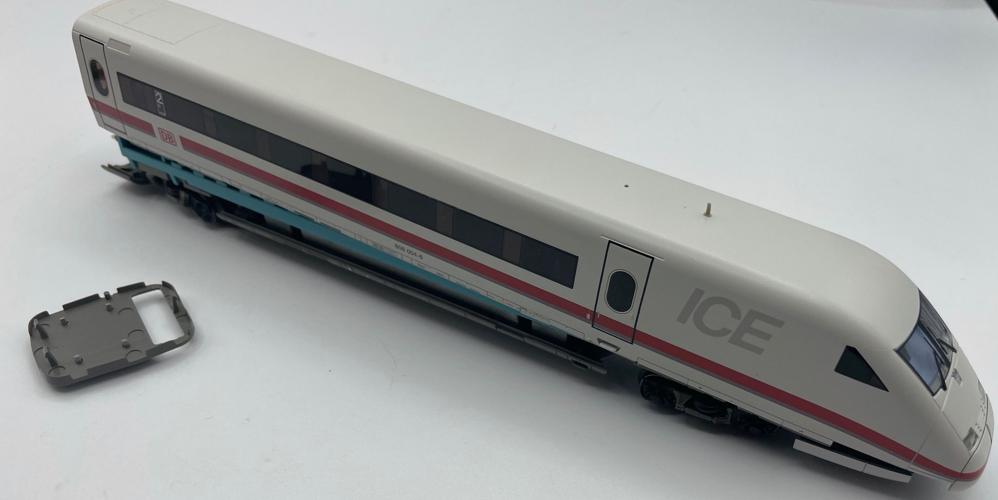
Now reassemble the coach: align the board and check that no cables can get trapped against the roof. Then put the roof on and push the bellows back into place.
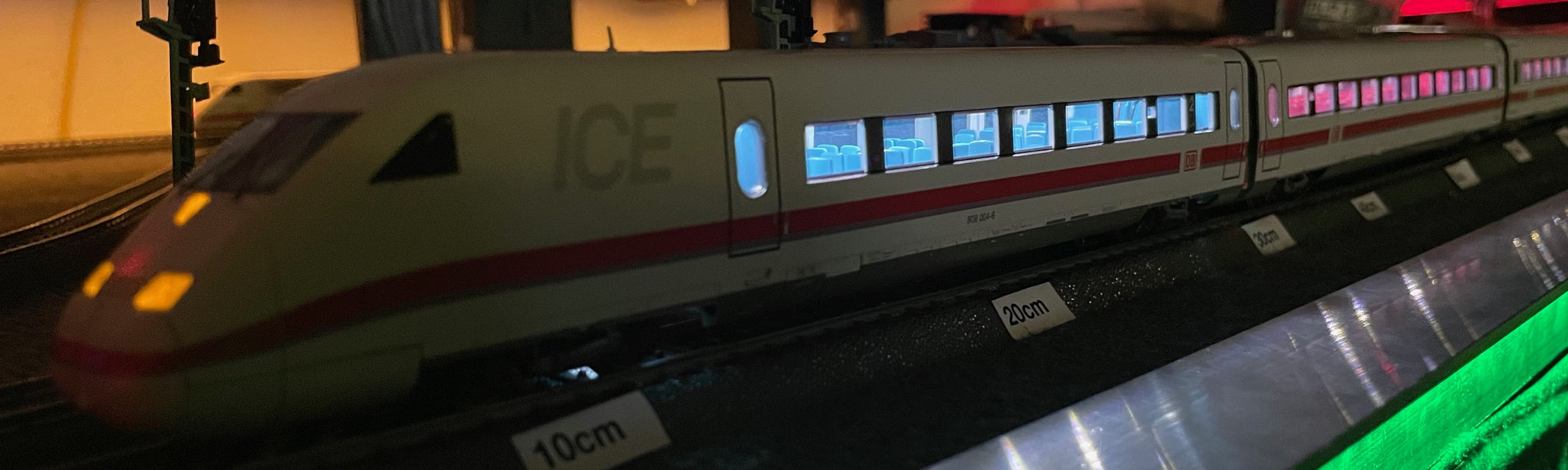
5. Technical data
Dimensions of the LoDi-(Motor) WiB ICE-M-S:
Length 180 mm
Width 29 mm
Thickness 1.55 mm
Weight: 18 grams, or 19 grams for the (-S) variant.
Dimensions of the LoDi-WiB ICE2-St:
Length 220 mm
Width 21 mm
Thickness 1.55 mm
Weight: 17 grams
The LoDi-Motor ICE-M(-S) has a standard 21-pin MTC interface and can be fitted with any common loco or function decoder with a 21-pin interface. Do make sure to use a decoder with amplified Aux 3 and 4 if you are using the version with pickup changeover.

Would you like to see the quality of the devices for yourself?
Get in touch with us HERE!
Visit our forum, where experienced users are happy to help you.