
Hardware
LoDi-Mono-Servo-DCC
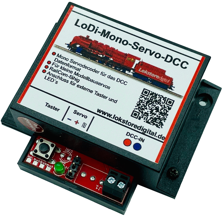
Simply a small servo decoder . . . For individual servos, quickly fitted, the
the LoDi-Mono-Servo-Dual can also be run without digital voltage, from DC or AC alone. Over RailCom the decoder can be read quickly and its CVs configured.
Features of the LoDi-Mono-Servo-DCC
- A single-channel servo decoder for small to medium servos.
- Connections for external push buttons and LEDs for a signal box panel.
- The decoder listens to the DCC format and can be read and configured over RailCom.
- Also usable stand-alone with DC or AC!
1. The LoDi-Mono-Servo-DCC and its connections
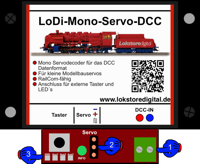
- (1) Connection to DCC, that is to a booster, feedback module or directly to a command station.
- (2) Connection for servos with a 3-pin plug.
- (3) A push button for external operation and external LEDs for position indication can be connected here.
2. LEDs and button on the LoDi-Mono-Servo-DCC
The LoDi-Mono-Servo-DCC has one LED, which we call INFO. It shows the following status by flashing:
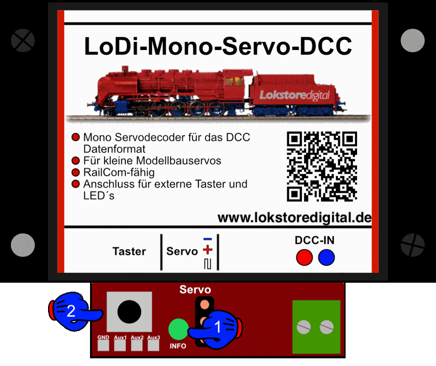
- (1) When the DCC signal comes on, the info LED flashes briefly, after which it stays lit. As soon as the decoder receives a valid command for itself, the LED flashes three times briefly. CV requests over RailCom are likewise shown with a triple flash.
- (2) The button is for programming the DCC base address. It can also be used for manual operation.
3. Connecting to DCC
As mentioned above, the LoDi-Mono-Servo-DCC can be connected to several power sources.
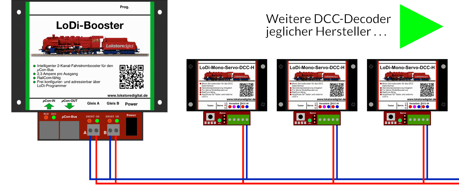
The first example shows it connected to a LoDi-Booster.
CAREFUL! For reliable switching of DCC accessories, a separate circuit or booster output should always be used. One booster output can run 40 LoDi-Mono-Servo-DCC units. (With decoders that need their own transformer current, the number is over 150 depending on the manufacturer, since the LoDi-Booster then only has to provide the data for the decoder.)
The LoDi-Mono-Servo-DCC takes the current for switching directly from the booster. As a rule a servo needs no more than 100 mA for small tasks. Because DCC commands are processed one after another, there are no problems with the power provided even with many switching tasks.
4. Connecting the servo
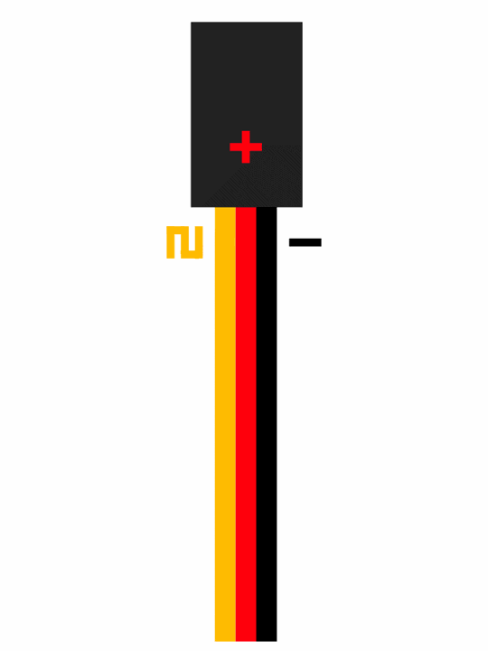
In most cases a servo has a cable with three conductors.
These are:
- Yellow or orange, which carries the data signal
- Red, carrying 5 volts, which supplies the servo with the voltage it needs.
- Black or brown, which carries the servo's common.
The colours can differ, however, so check your servo's documentation if you are unsure.
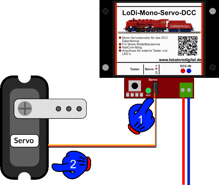
At (1) you now see the connection for the servo on the decoder. Negative is at the top. The socket is simply pushed straight onto the decoder's pins. (2) represents the servo.
5. CV list and settings
The LoDi-Mono-Servo-DCC is set through CVs.
If you have the LoDi-Rektor with a LoDi-Booster or CDE booster connected, you can write the CVs over PoM (programming on main) with the LoDi-ProgrammerFX from version 2.2.
The decoder can equally be programmed with any conventional command station that has a DCC programming output or handles PoM.
Setting the DCC address: you have now installed the decoder successfully, the DCC cable is plugged in, and the LoDi-Mono-Servo-DCC
now glows green continuously to show it is ready.
As delivered, the decoder responds to turnout or accessory address 1.
If you want to change an address quickly, proceed as follows: there is a programming button on the decoder as described above. Press it for 3 seconds. The decoder starts to flash quickly, telling you it is ready for a new address.
Now send the new address from the control software, directly at a command station or in the LoDi-ProgrammerFX (the LoDi-Rektor is required), in the turnout field under DCC.
The decoder takes the address and stops flashing. From now on it is reachable at the address you chose.
Setting the CVs: as mentioned several times, the LoDi-Mono-Servo-DCC can be programmed over PoM (programming on main). In most applications there are three CVs to consider.
1 × position A = CV 33, value 0–255
2 × position B = CV 34, value 0–255
3 × speed = CV 41, the speed at which the servo moves, 0–255
These values can be read back later over RailCom.
6. Stand-alone version
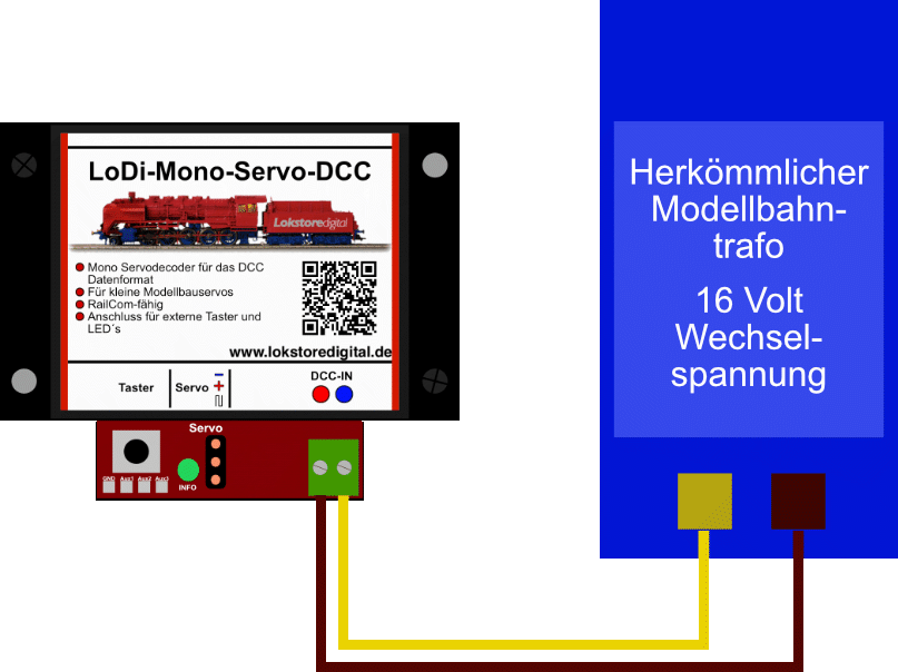
Thanks to the stand-alone version, the decoder can be supplied with ordinary DC up to 20 volts and AC up to 16 volts.
It should first receive its information, such as servo positions 1 and 2, from a command station, and the speed should be set.
7. Connecting external push buttons
The LoDi-Mono-Servo-DCC has a button of its own which, as described above, is used to set the digital address. A short tap of the button switches the position between A and B, throwing a turnout manually, for instance.
In addition the decoder can be operated through an external button. It makes no difference whether it runs on digital or analogue power.
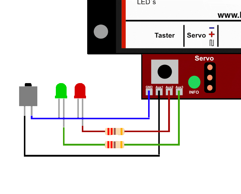
There are four solder pads on the decoder.
From left to right:
1. GND = common, blue in the diagram.
2. Aux1 = external button, which has to be switched against the common, black in the diagram.
3. Aux2 = external LED for position 1 (Aux switches +; a 220 ohm series resistor is also needed).
4. Aux3 = external LED for position 2 (Aux switches +; a 220 ohm series resistor is also needed).
Instead of a push button, a toggle switch can be used to change the position. That then has to be set in CV 11.
8. Technical data
| Property | Value |
|---|---|
| Dimensions | Length 5.6 cm |
| Width | 6.8 cm |
| Height | 2.5 cm |
| Weight | 31 grams |
In digital operation the decoder can be run at up to 22 volts.
Do mind the specifications of your command station or booster manufacturer here.
The decoder can be run on 20 volts DC or 16 volts AC.
Loadable by a servo with 1 ampere peak and 400 mA continuous