
Hardware
LoDi-21MTC(-S)
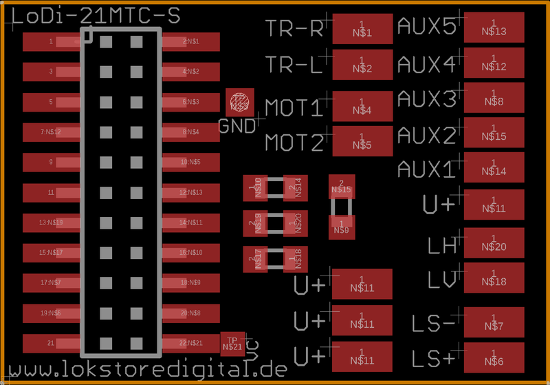
The LoDi-21MTC(-S) board
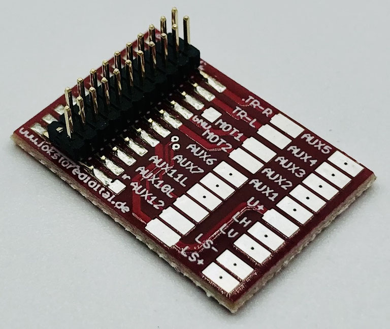
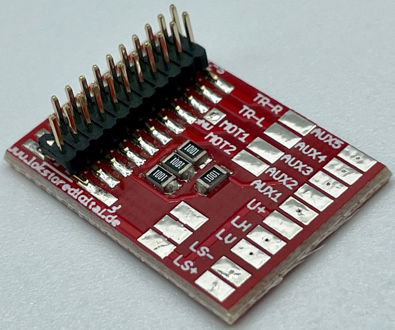
The LoDi-21MTC(-S) board. Would you like to convert your old locomotives simply and quickly, without having to do without the latest decoder technology?
With the LoDi-21MTC board, converting older locomotives cleanly and quickly is child's play . . .
And now even the LoDi-21MTC-S board with built-in series resistors ! ! !
When converting locomotives you want to be as flexible as possible.
That is why we developed the LoDi-21MTC(-S) board and brought all 21 poles out to solder pads.
It is suitable for boards with or without sound.
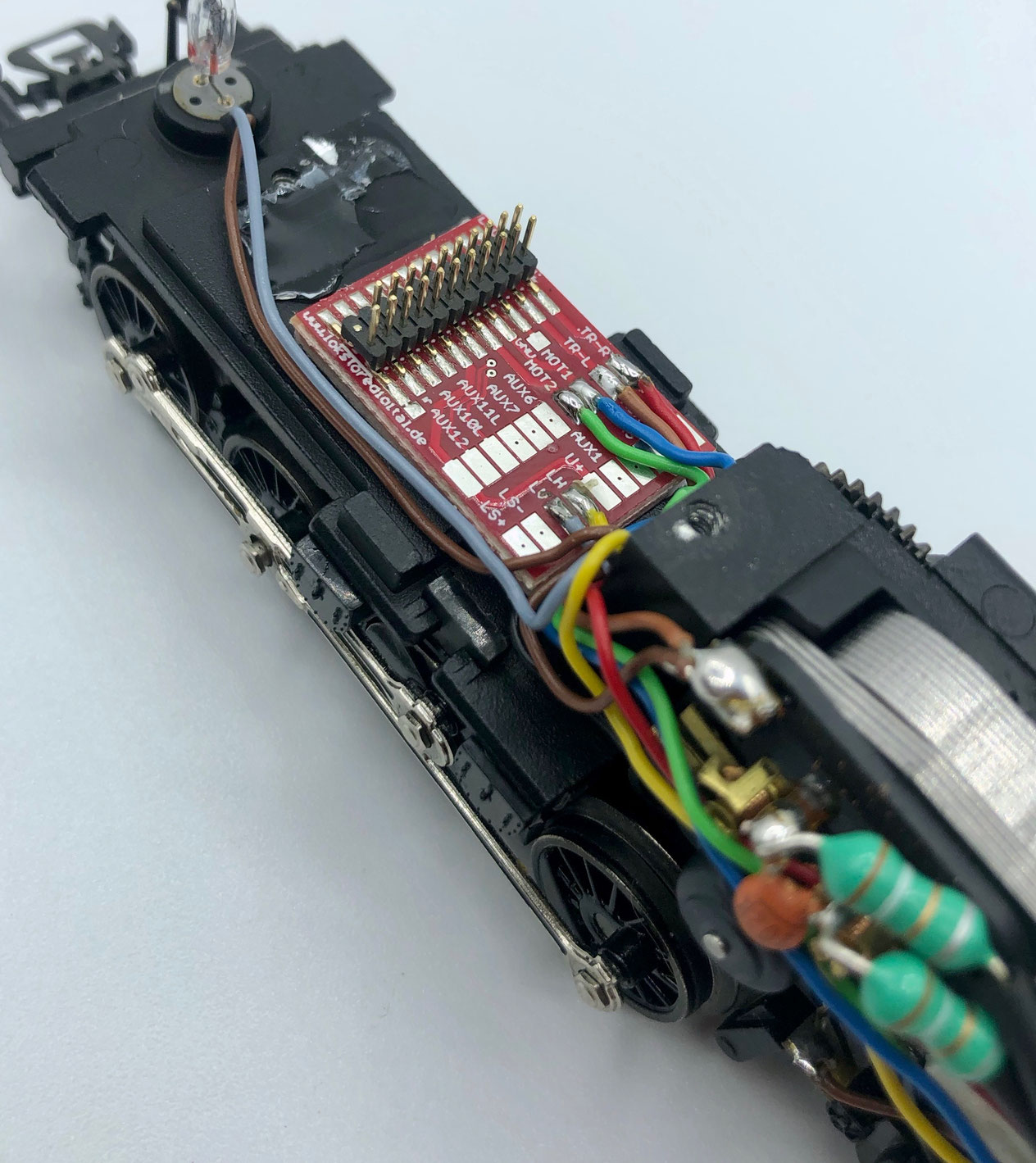
Features of the LoDi-21MTC board
- A simple 21-pin MTC interface for all common 21-pin locomotive and sound decoders
- A space-saving design
- All poles brought out to solder pads
- Independent of gauge or two- and three-rail system
1. The LoDi-21MTC board and its connections
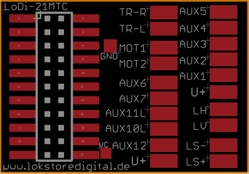
Connection information, NMRA colour scheme:
- TR-R = right-hand rail = red
- TR-L = left-hand rail = black
- MOT 1 = motor right = orange
- MOT 2 = motor left = grey
- LV = front light = white
- LH = rear light = yellow
- U+ = shared + = blue
- AUX1 = switchable channel 1 = green
- AUX2 = switchable channel 2 = purple
- LS− / LS+ = loudspeaker = brown
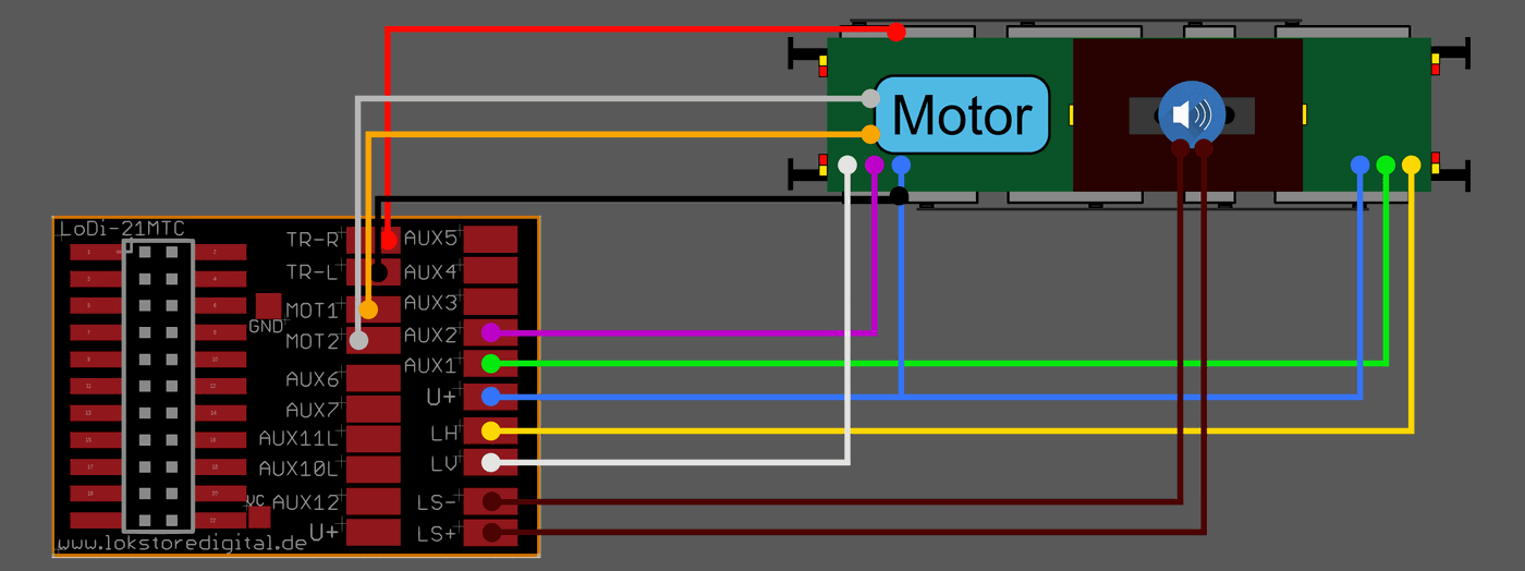
An example wiring diagram with a locomotive. Front and rear lights with directional lighting, switchable through AUX1 and AUX2.
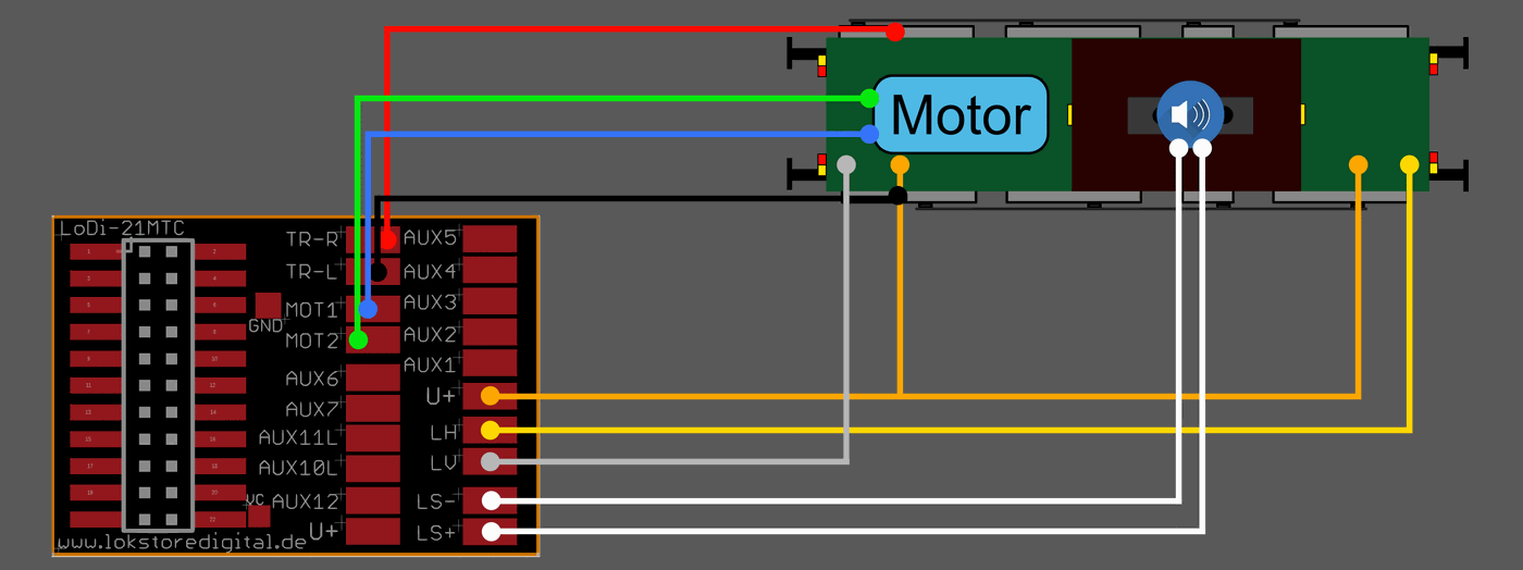
Connection information, Märklin® colour scheme:
- TR-R = right-hand rail = red
- TR-L = left-hand rail = brown
- MOT 1 = motor right = green
- MOT 2 = motor left = blue
- LV = front light = grey
- LH = rear light = yellow
- U+ = shared + = orange
- AUX1 = switchable channel 1 = brown-red
- AUX2 = switchable channel 2 = brown-green
- AUX3 = switchable channel 3 = brown-yellow
- AUX4 = switchable channel 4 = brown-white
- LS− / LS+ = loudspeaker = white
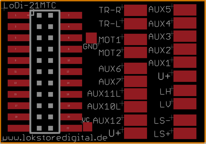
The LoDi-21MTC board has further outputs which can be used differently depending on the manufacturer, such as SUSI or further AUX or logic channels.
CAREFUL! The board must not be mounted directly onto the metal of the locomotive; the locomotive and the board have to be insulated from each other. For a perfect fixing, use foam adhesive tape to fasten the board in the locomotive. Using double-sided adhesive tape also ensures the locomotive body and the board are insulated.

2. The LoDi-21MTC-S board and its connections
On the LoDi-21MTC-S board we have done without the higher outputs such as AUX6–AUX12. These are mostly logic outputs or are used in manufacturer-specific ways.
We have used the space for series resistors. That means the board can be used directly in locomotives with LEDs. You do not have to add any resistors on top.
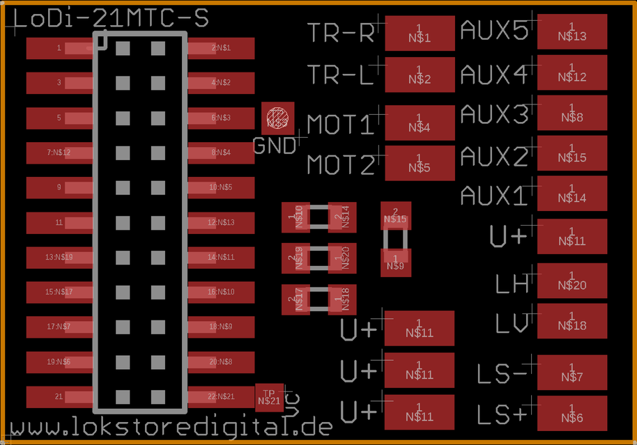
Connection information, NMRA colour scheme:
- TR-R = right-hand rail = red
- TR-L = left-hand rail = black
- MOT 1 = motor right = orange
- MOT 2 = motor left = grey
- LV = front light = white, 1k built in
- LH = rear light = yellow, 1k built in
- U+ = shared + = blue
- AUX1 = switchable channel 1 = green, 1k
- AUX2 = switchable channel 2 = purple, 1k
- LS− / LS+ = loudspeaker = brown
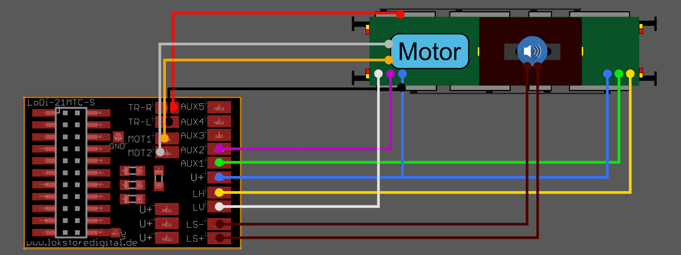
Here we have now fitted LEDs with directional lighting in the locomotive, using 4 light channels. On the LoDi-21MTC-S, 1 kilohm resistors are fitted at F0V/H as well as at AUX1 and AUX2. You therefore do not have to fit any additional resistors for the directional lighting in the locomotive.
Connection information, Märklin® colour scheme:
- TR-R = right-hand rail = red
- TR-L = left-hand rail = brown
- MOT 1 = motor right = green
- MOT 2 = motor left = blue
- LV = front light = grey, 1k built in
- LH = rear light = yellow, 1k built in
- U+ = shared + = orange
- AUX1 = switchable channel 1 = brown-red, 1k
- AUX2 = switchable channel 2 = brown-green, 1k
- AUX3 = switchable channel 3 = brown-yellow
- AUX4 = switchable channel 4 = brown-white
- LS− / LS+ = loudspeaker = white
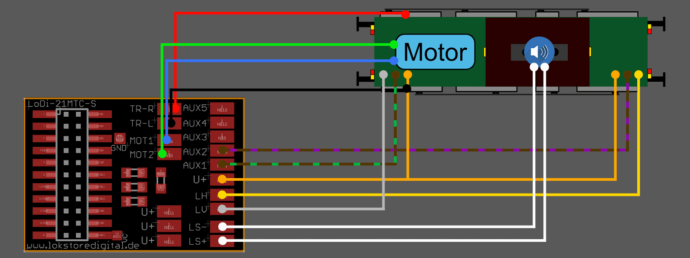
In this example we have removed a board from a Märklin locomotive and left the original LED lighting in place. The series resistors would now be missing here, which we now have again with the LoDi-21MTC-S, so no additional resistors have to be added.
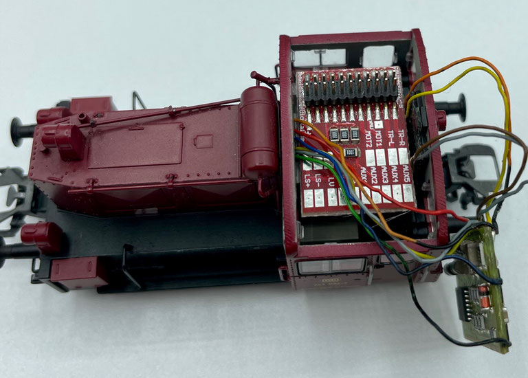
Here is a small example of the LoDi-21MTC-S in a Märklin Köf, where the old Motorola decoder is removed and replaced by a 21-pin decoder of your choice.
3. Technical data
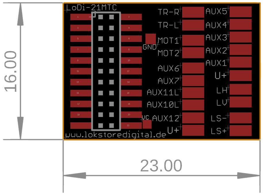
LoDi-21MTC
0–24 volts AC, DC or digital
Dimensions
Length: 23 mm
Width: 16 mm
Height: 13 mm at its highest point (can vary from decoder to decoder)
Weight: 2 g
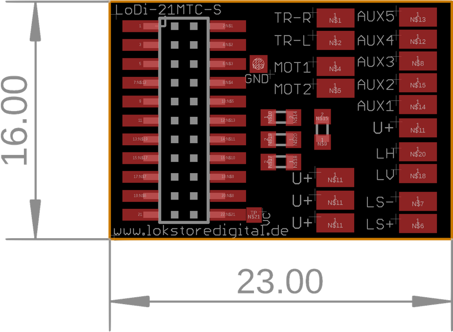
LoDi-21MTC-S
0–24 volts AC, DC or digital
Dimensions
Length: 23 mm
Width: 16 mm
Height: 13 mm at its highest point (can vary from decoder to decoder)
Weight: 2 g

Would you like to see the quality of the devices for yourself?
Visit our forum, where experienced users are glad to help.