
Hardware
LoDi-WiB ICE Exp
LoDi-(Motor) WiB ICE Exp
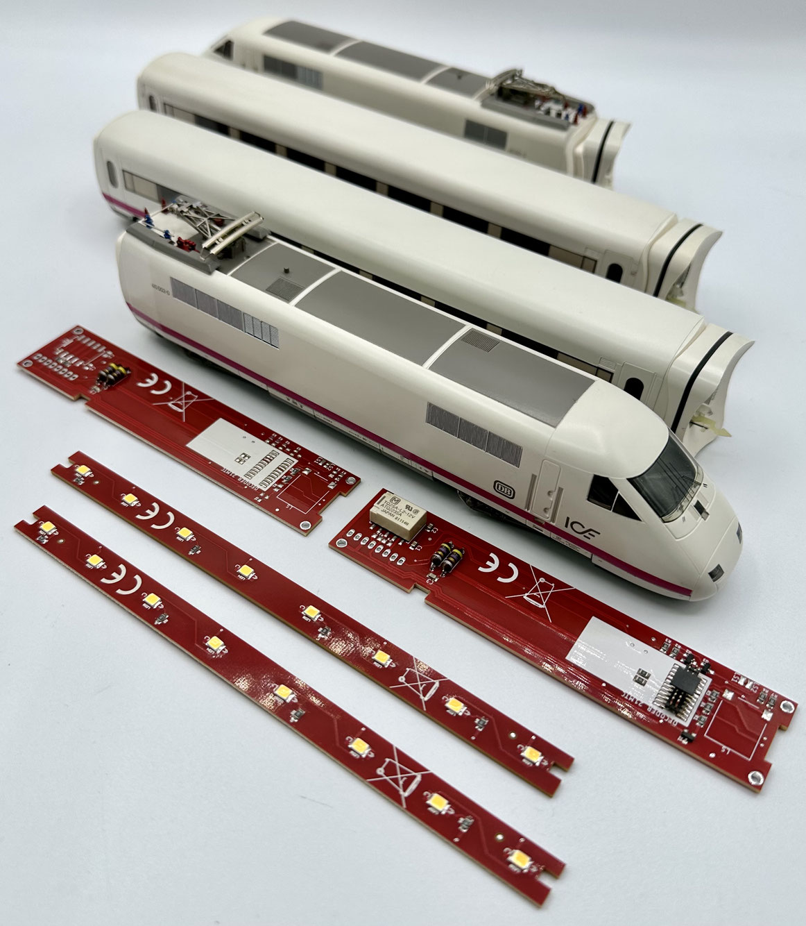
The LoDi-Motor WiB ICE Exp conversion — a new life for the Märklin ICE Experimental. The Märklin ICE Experimental is a model train that holds a special place for many collectors and enthusiasts. As the forefather of the ICE era, it has a charm all of its own.
Now there is a way to bring this historic train up to the latest state of the art: the LoDi-Motor WiB ICE Exp conversion for the power cars and the LoDi-WiB ICE Exp for the intermediate coaches.
The LoDi-Motor WiB ICE Exp conversion is a set developed specifically for the older models in the Märklin ICE Experimental range (3371, 3771, 3671). With this set your trains can be converted to a modern 21-pin MTC interface and also get a ready-made place for a loudspeaker. The conversion is available in two versions, with or without pickup changeover.
Even then, the models in the Märklin ICE Experimental range had special features: two coreless motors with a flywheel, 8-pole couplings movable in two axes, bellows for the coaches and an extremely sturdy construction.
The LoDi-Motor WiB ICE Exp conversion is a great way of upgrading the Märklin ICE Experimental and adapting it to the modern demands of a model railway. That preserves the train's nostalgic charm while letting you use the benefits of today's technology at the same time. This conversion set is an affordable alternative for everyone who owns a Märklin ICE Experimental.
Features of the LoDi-(Motor) WiB ICE Exp (-S)
- Simple installation, optimised for vehicles with full RailCom capability.
- A precisely fitting design for the power car, the coach and the trailer.
- The 21-pin MTC standard for connecting any decoder, with provision for a loudspeaker.
- Economical LED technology, perfectly lighting the ICE Experimental.
1. Before we begin...
A few notes before we start the conversion...
You can start the pictures as a small slideshow and enlarge them for a detailed view.
We will guide you step by step through a successful coach conversion with this description.
If you notice during the conversion that steps or information are missing, do get in touch with us or visit our forum.
If you can solder and have already lit one coach or another, the conversion should come easily to you. If you are a beginner, however, or do not feel up to a conversion, do get in touch with our partners.
They will be glad to make you an individual offer.
You can carry out the conversion yourself?
Then let us begin.
You will need:
- a soldering iron with a fine tip, and solder.
- a desoldering pump or desoldering braid.
- a flat screwdriver and a pair of tweezers.
- a small, fine pair of side cutters as well as, if available, a wire stripper for fine cores.
- superglue if needed.
2. The LoDi-Motor WiB ICE Exp (-S)
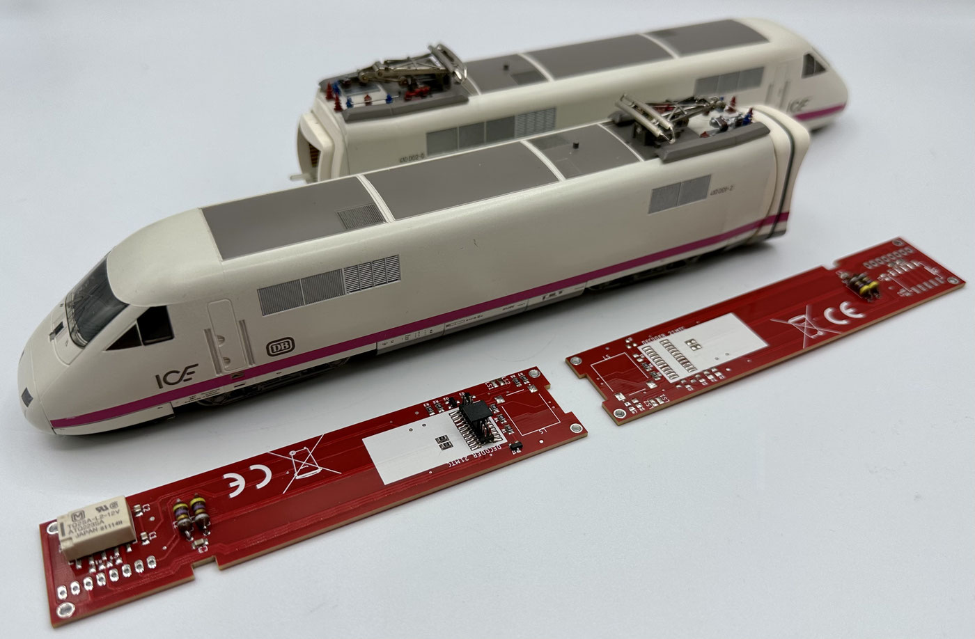
In our shop you can choose between a complete set and individual LoDi-Motor WiB ICE Exp boards. The set also contains the dummy board for the second power car; no decoder has to be plugged onto it.
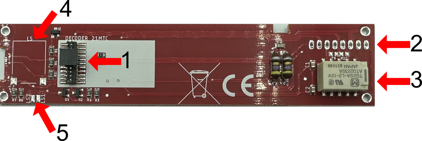
First we would like to explain the boards. To do that we start by looking at the underside of the LoDi-Motor WiB ICE Exp.
- The 21-pin MTC interface. This is where the decoder is plugged in.
- The coupling's original ribbon cable is soldered in here.
- The relay for switching the pickups over, only on the LoDi-Motor WiB ICE Exp-S.
- A place to connect a loudspeaker.
- An additional connection for a loudspeaker.
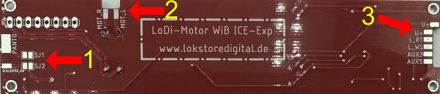
The top of the board, seen from above
- Here you can decide whether you want to supply the train through solder bridge SJ1, the pantograph, or SJ2, the pickup.
- The motor is connected at this point.
- A connection for the front (white/red light, AUX 3 for the cab, for instance, AUX 5 for the pantograph flasher).
AUX 3 and 5 can be loaded with 150 mA.
Now let us begin the conversion.
First the power cars have to be taken apart.
To take the train's body off, start by proceeding as follows:
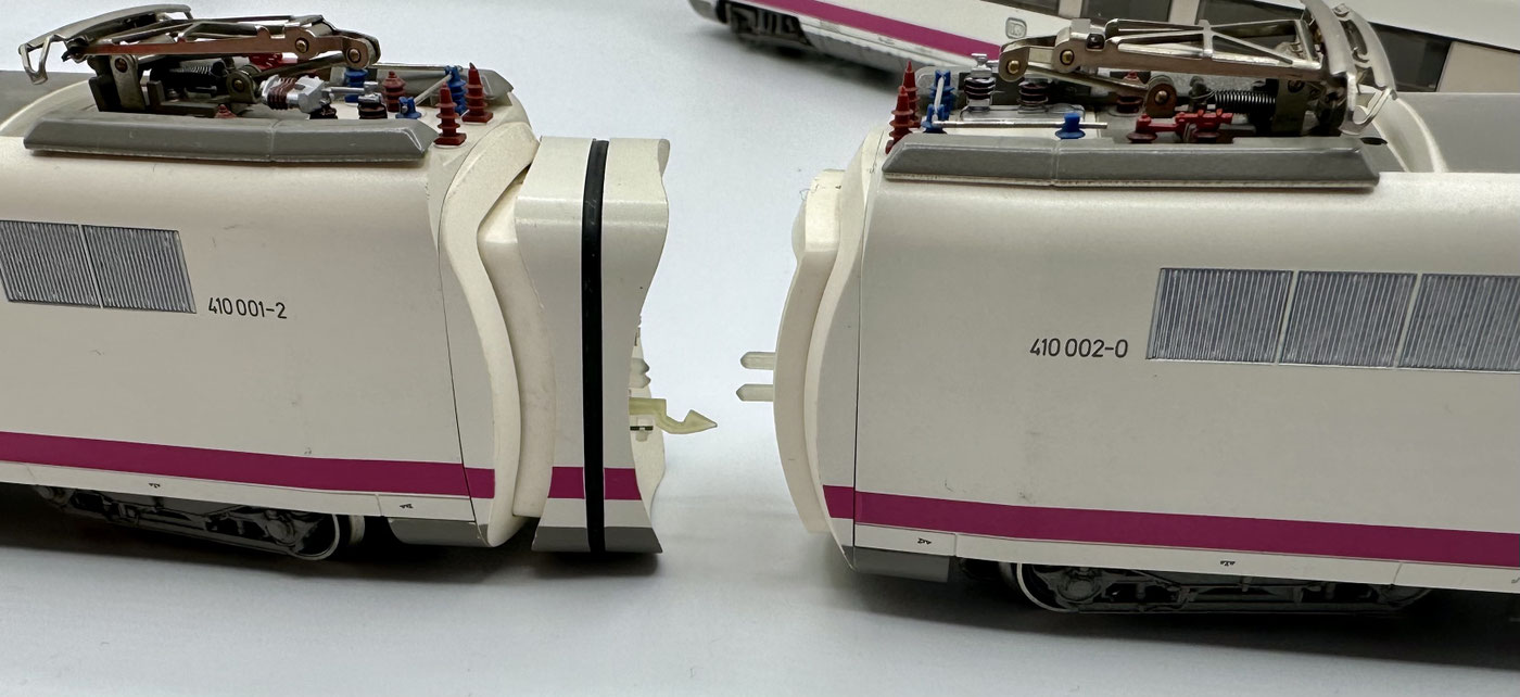
On the first power car, remove the coach bellows. Then turn the power car onto its side. You will now see a notch, which can be eased apart a little very nicely with a medium-sized flat screwdriver. The cover can then simply be taken off.
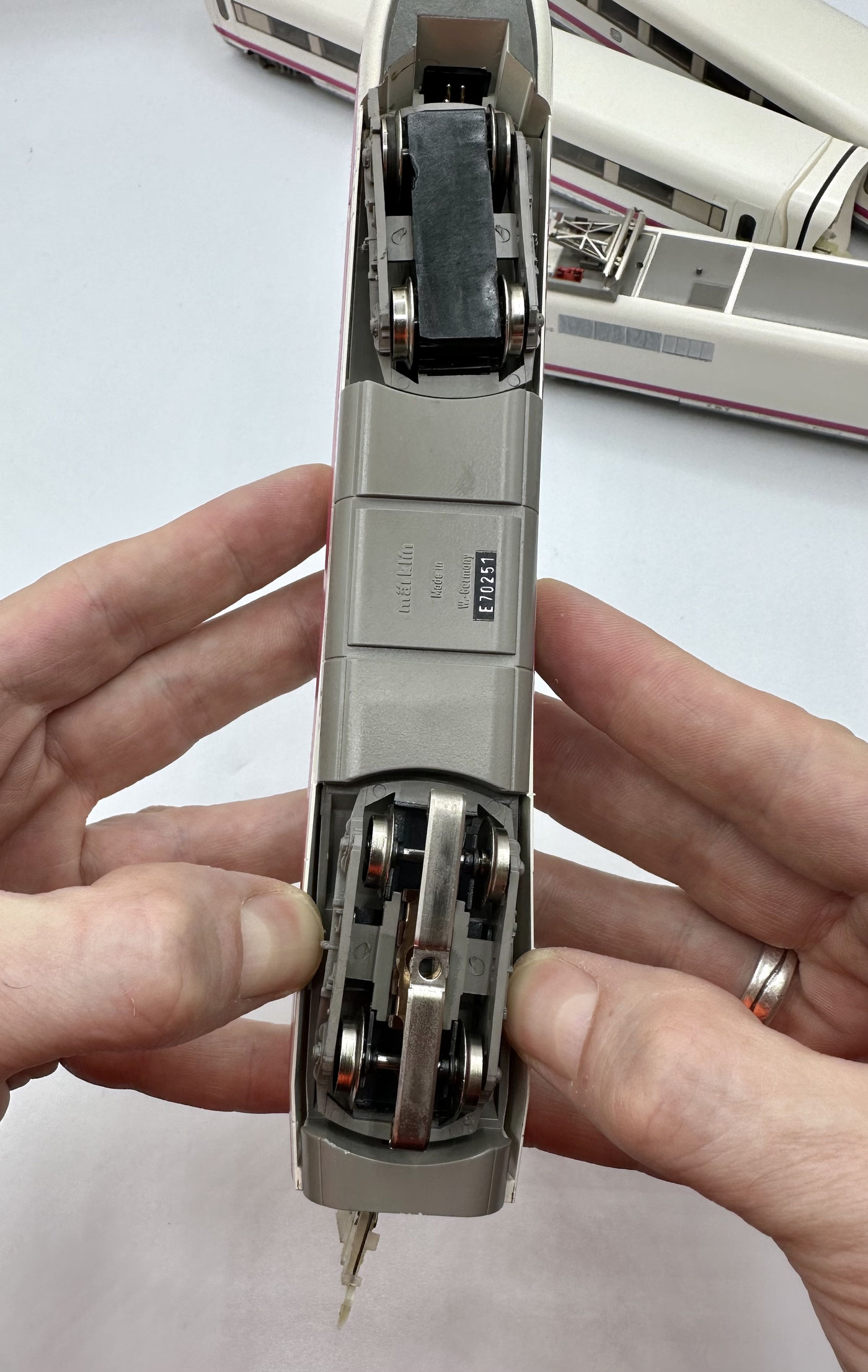
Next, at the rear bogie, the power car's body has to be bent outwards a little; you should hear a slight click, which means the roof has come free of the lower mounting.
The roof can now simply be taken off.
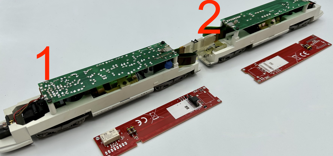
Of the two power cars there is a main power car (the female coupling in picture 1), which takes the decoder board, and a further power car (male coupling, 2), in which only the LoDi-Motor WiB ICE Exp without an interface is fitted.
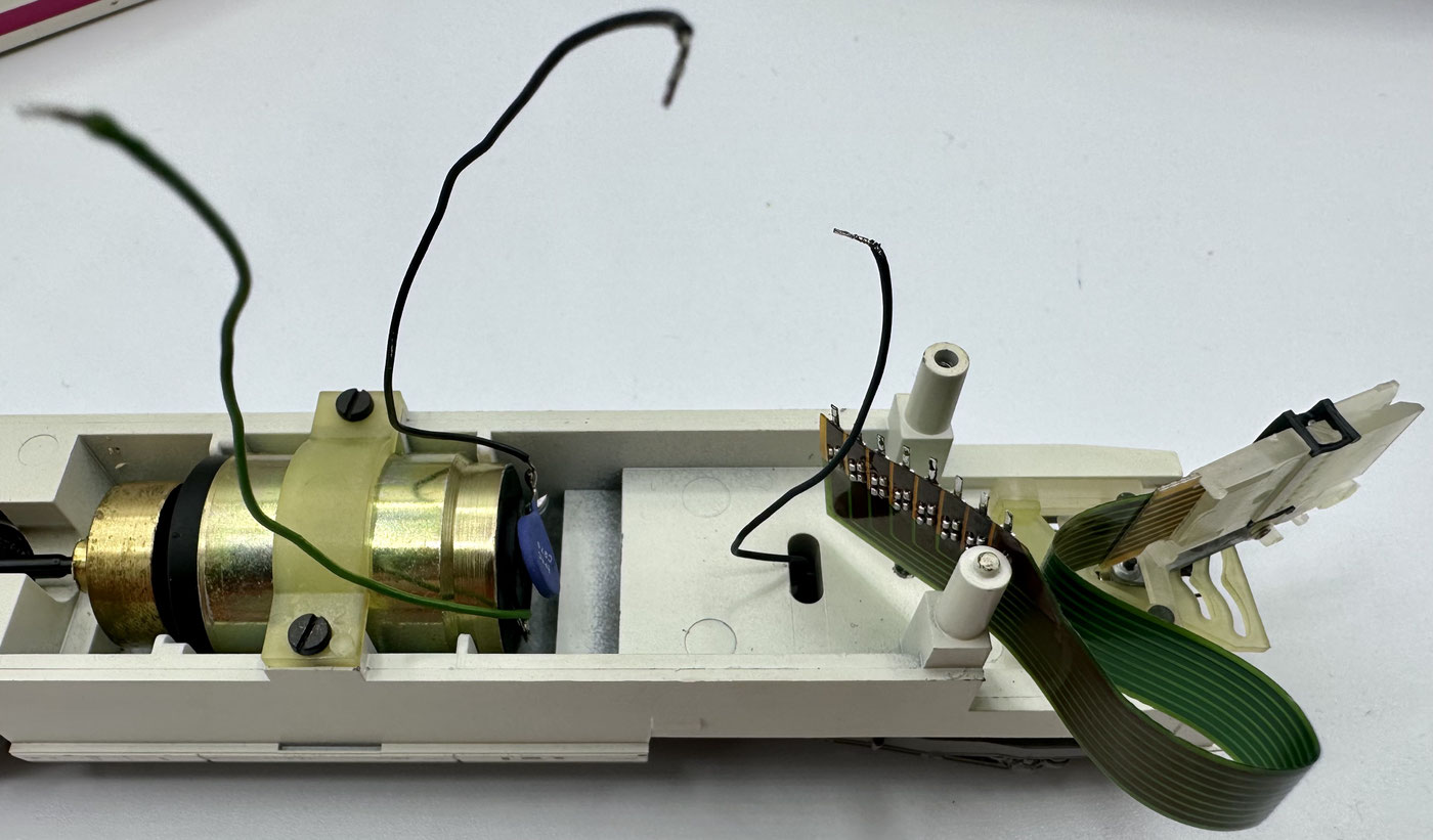
Unsolder all the wires from the original board.
In most cases they can simply be used again.
The ribbon cable should be desoldered carefully with a desoldering pump or desoldering braid. Take care that the soldering iron is not set too hot, or the flexible board could be damaged.
(On some versions of the train a PTC was fitted directly at the motor. It has to be desoldered and the wire connected directly to the motor.)
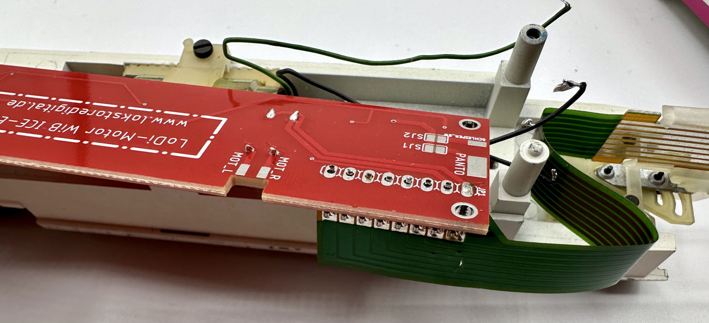
Now that the power car is clear, the new board can be fitted. Thread the 8-pin header to which the coupling is attached into the board and fix it with one solder point. Solder the further solder points one after another. Install the decoder of your choice right away; in the picture you see an ESU LokSound with a loudspeaker. There is already a place for it on the board and it can be soldered straight onto the board.
After that the two wires from the motor as well as the pickup are soldered to the boards and fixed again with the two screws.
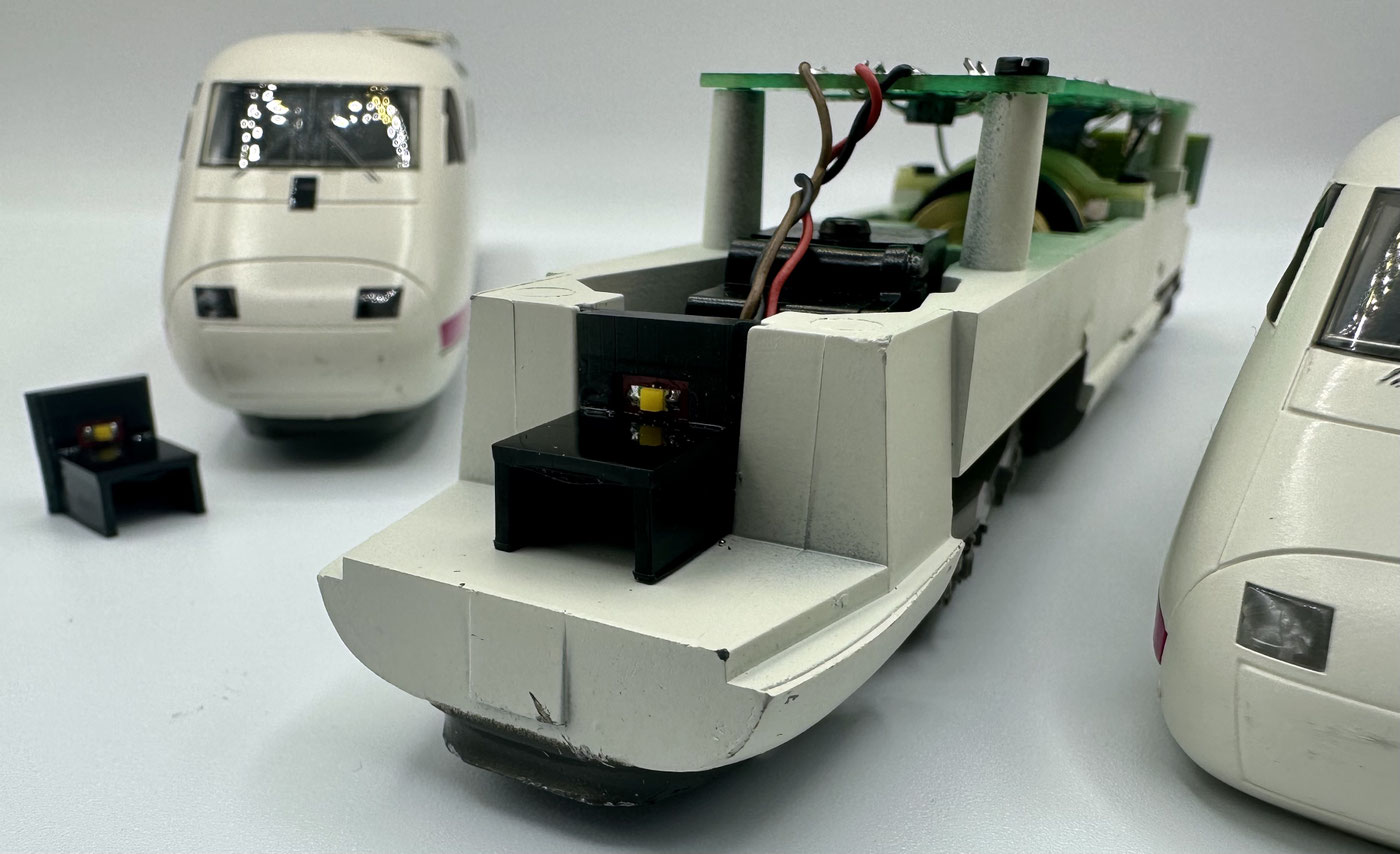
On the ICE Experimental the front lamps can be replaced by LEDs.
The necessary series resistors are already built into the LoDi-Motor WiB ICE Exp.
If you do want to keep using the lamps, however, you have to bridge resistors R4 and R5 on the board.
In this case, though, we are using the LoDi-WiB ICE-M front, which fits the ICE 1 as well as the ICE Experimental.
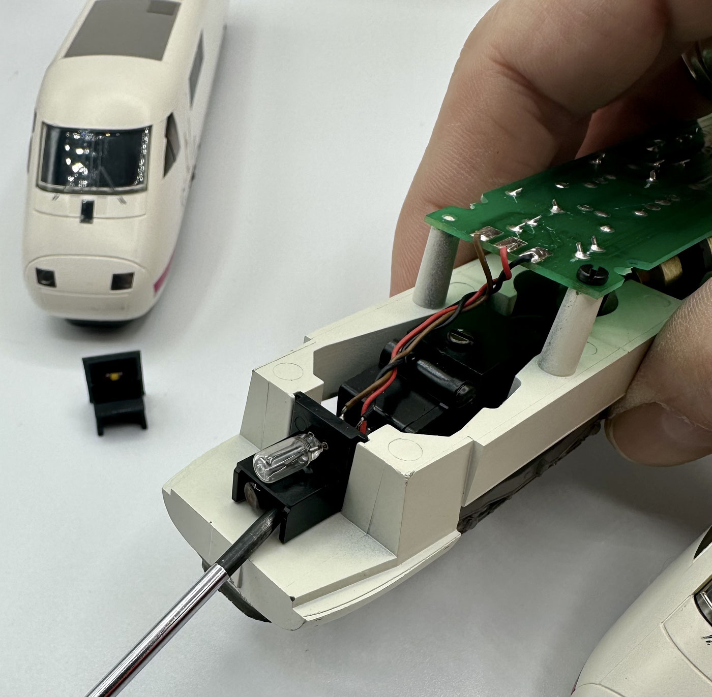
To remove the original lighting, place a screwdriver gently at the front and lever the old lighting unit out. For connecting we use the original wires, which we unsolder from the lighting unit and solder to the new LoDi-WiB ICE-M front.
Brown wire = VCC > U+
Red wire = Red > L_RT
Black wire = white > L_WS
Once all the wires are soldered on, the lighting unit can be pushed back into the power car's holder.
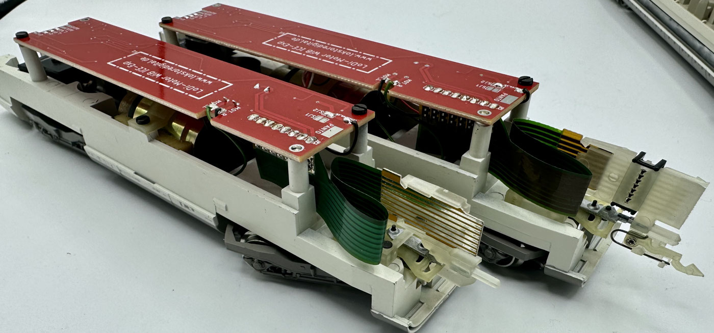
With the main power car converted, the board without an interface has to be installed in the other power car. Proceed as with the main power car. Take care that the lighting's connecting wires as well as the motor connection have to be swapped so that the car runs in the same direction as the main power car.
Likewise the tail light should of course glow red when the light on the main power car is white. So simply swap the lighting connections as follows: brown wire = VCC > U+
Red wire = Red > L_WS
Black wire = white > L_RT
The decoder fitted has to be one without amplified AUX 3 and 4, so not an MKL. The function mapping of the AUX outputs is as follows: F0 = red/white directional lighting, AUX 1 = pickup changeover position 1
AUX 2 = pickup changeover position 2
AUX 3 = output at the front (cab lighting), 150 mA
AUX 4 = output for coach lighting, total load 1.5 amperes. AUX 5 = output at the front (pantograph flasher), 150 mA
If the motor no longer runs properly...
3. The LoDi-WiB ICE Exp (-S)
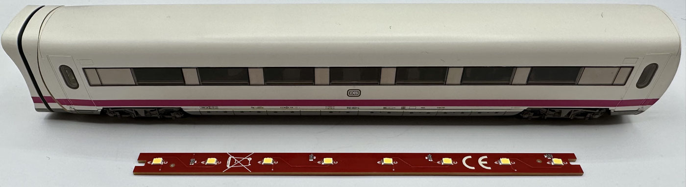
Fitting it into the coach itself is very easy to handle, as you will see in the rest of the description.
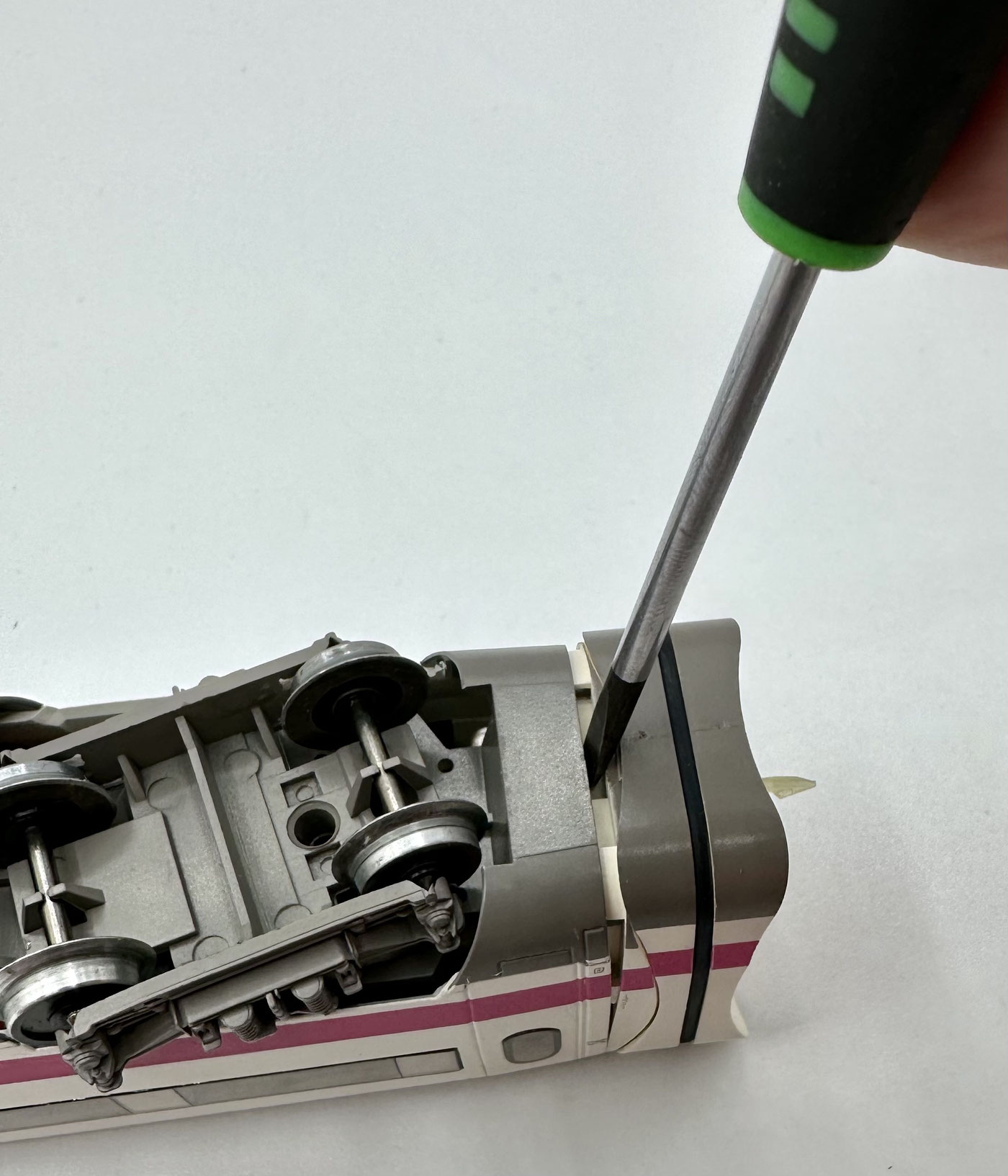
As with the power cars, the coach too has retaining clips at both ends which have to be levered out from below.
Once both retaining jaws are removed, the coach has to be pressed apart a little at the bottom; the body should then come off.
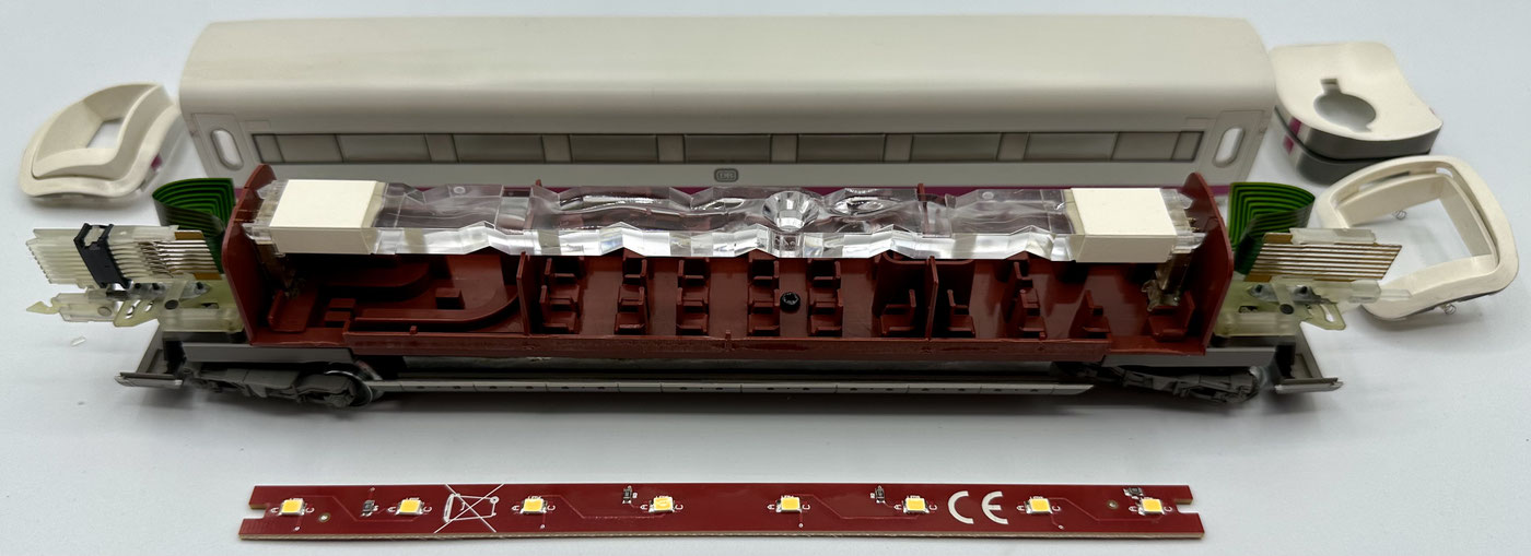
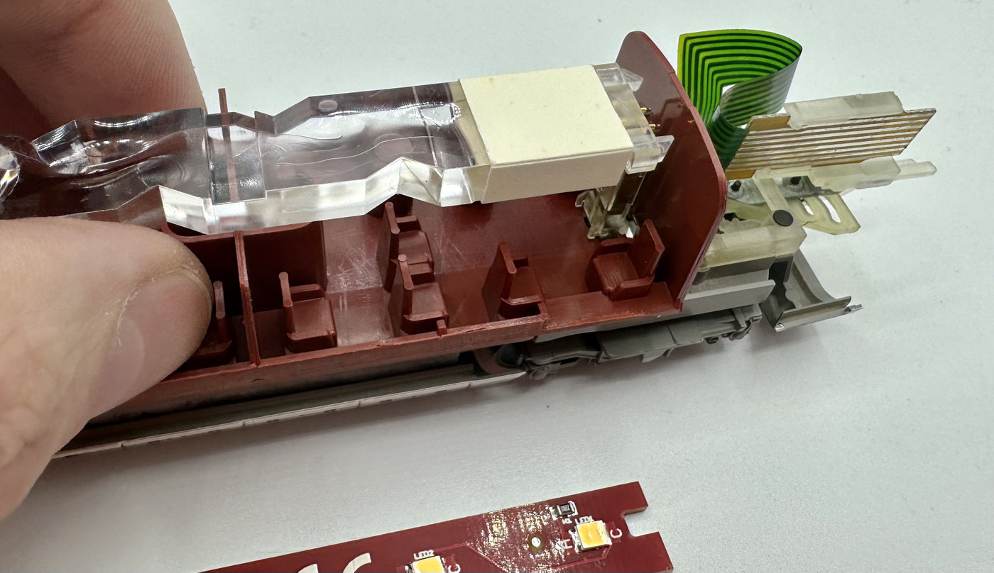
Now that the coach roof is off, the original lighting first has to be removed.
The retaining posts on which the original lighting is mounted should stay in the coach. We will install the LoDi-WiB ICE Exp on them later.
Pull carefully at the lighting unit and hold the post firmly as you pull the original lighting unit off.
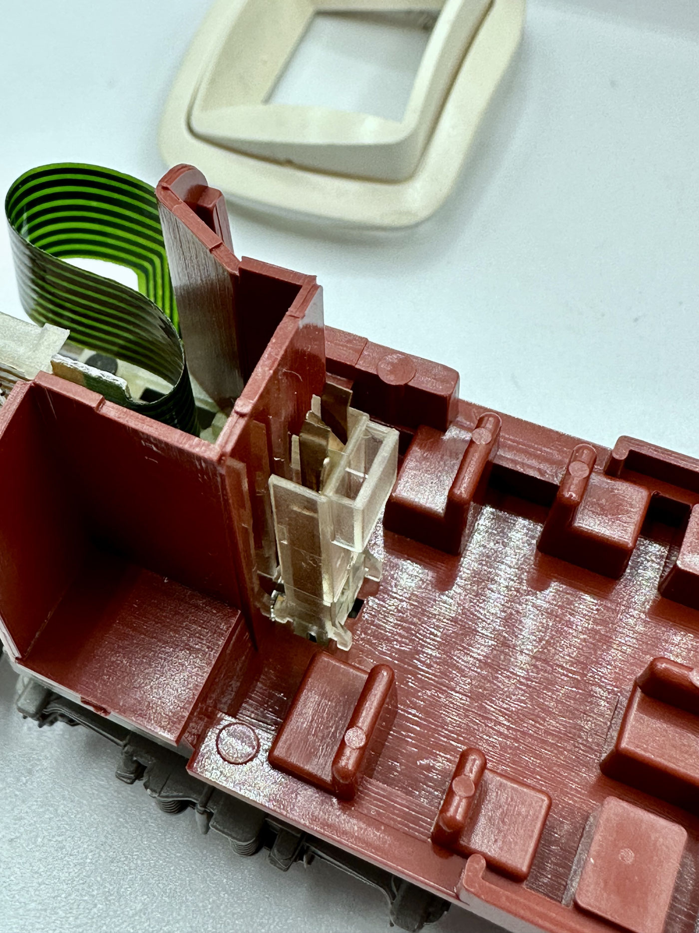
Ideally the whole thing now looks like this: the posts stand upright. You can now put an extra drop of superglue onto the post as well. It is very brittle and therefore has to be handled very carefully.
Once it is fixed on both sides, 2 contacts on both retaining posts still have to be bent aside. Otherwise they get in the way when installing the new board.
The two contacts can be bent a little towards the outside of the coach very easily with a screwdriver, as can be seen in the picture.
If the mountings break off as you pull, despite all your care, do not worry: they can be fixed back on with a small blob of superglue.
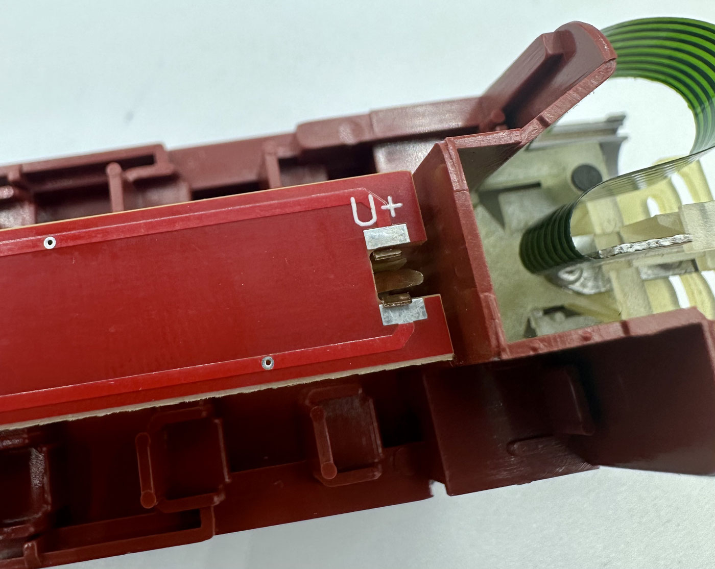
The LoDi-WiB ICE Exp can now be laid between the contacts. It is very important here that you watch for the correct marking for U+. As can be seen in the picture, it points towards the male coupling, to the right, with U+ at the top.
Now solder the contacts to the board.
Take care that, if you have used superglue in the coach to fix the mounting, you let the coach outgas sufficiently. Otherwise milky effects could appear in the coach glazing if the glue has not yet dried out.
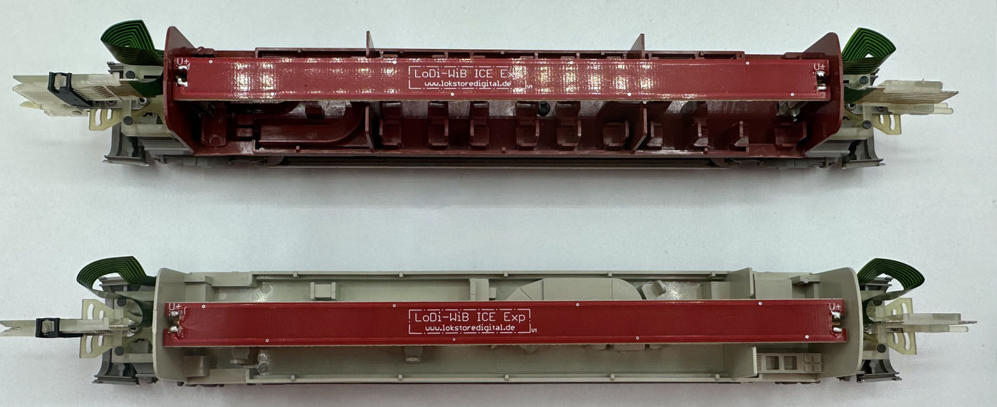
The board fits all original Märklin coaches made for the Experimental. After the conversion you can now fit the coach roof again and push the retaining jaws back in at the sides. The bellows go on the female side of the coach.

4. Technical data
Dimensions of the LoDi-WiB ICE Exp: length 170 mm, width 11 mm, thickness 1.55 mm. Weight: 7 grams. Dimensions of the LoDi-(Motor) WiB ICE Exp: length 124 mm, width 27 mm, thickness 1.55 mm. Weight: 13 grams, or 15 grams for the (-S) version.
The LoDi-(Motor) ICE Exp (-S) has a standard 21-pin MTC interface and can be fitted with all common locomotive or function decoders with a 21-pin interface.
For use with decoders without MKL (unamplified AUX 3 and 4).
5. LoDi-(Motor) WiB ICE Exp download
Here you can download a summary of the LoDi-(Motor) WiB ICE Exp as a PDF.