
Hardware
LoDi-WiB ICE3-M(-St)
LoDi-(Motor) WiB ICE3-M(-St)
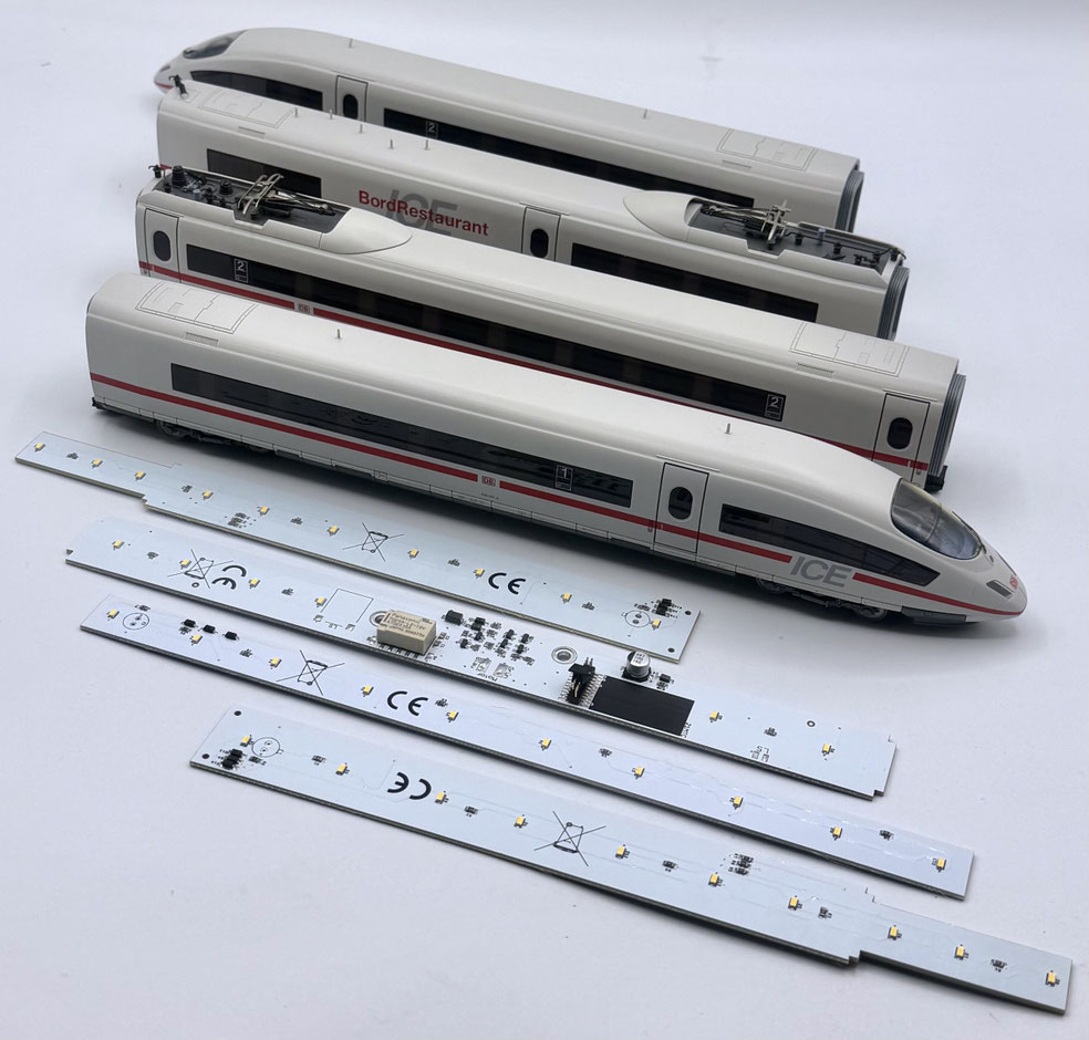
The ICE 3 from Märklin and Trix has been a fixture of countless model railway layouts for many years. The older versions in particular are still widespread and still convince with their looks and their running qualities. Technically, though, many of these trains come from a time when analogue control, filament bulbs or early Motorola decoders were the standard.
That is exactly where our LoDi-WiB system for the Märklin and Trix ICE 3 comes in. It is not simply new lighting, but a complete replacement of the original boards in the train. That turns a technically outdated model back into an up-to-date ICE 3 which fits into modern digital layouts without trouble. Analogue trains too can be run digitally for the first time this way, while older decoders can be replaced with current technology.
Despite the many ICE 3 versions Märklin have produced over the years, the train is built on a very uniform platform. That is exactly what we take advantage of: our boards are designed so that they can be used in all Märklin ICE 3 versions, regardless of the year of manufacture or the original equipment. The conversion is clean, with no makeshift solutions and no compromises in operational reliability.
The result is an ICE 3 that convinces visually, is technically up to date and serves reliably on modern, RailCom®-capable digital layouts too, whether it is an old collector's piece or a long-standing resident of the layout.
Features of the LoDi-WiB ICE3-M(-ST), LoDi-Motor WiB ICE3-M and -S
- A precisely fitting replacement for the original boards
- A 21-pin MTC interface for modern decoders
- Support for modern RailCom®-capable digital layouts
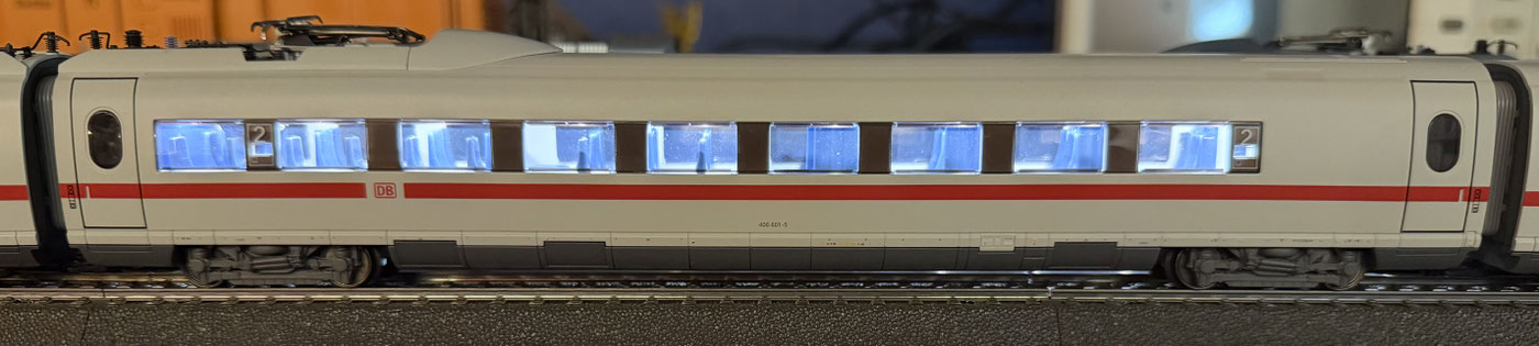
- Power-saving LED technology with even illumination
- One system for all Märklin and Trix ICE 3 versions, regardless of the year of manufacture
- Better illumination, especially in the driving trailers
1. A short introduction to the boards, and connection information
In our shop you can choose between individual boards and sets; in detail we explain the following boards:
1. The LoDi-WiB ICE3-M for the compartment coaches
2. The LoDi-WiB ICE3-St for the driving trailers
3. The power car board LoDi-Motor WiB ICE3-M (-S), where the S stands for pickup changeover.
The layout, and where which wires have to be connected. Here you will now find the list of article numbers of the Märklin and Trix ICE 3 our board can be run with. If your article number is not among them, do get in touch with us.
The LoDi-(Motor) WiB ICE3-M(-ST) fits the following Märklin® coaches, power cars and driving trailers:
- Märklin 34780 – ICE 3M electric multiple unit, class 406
- Märklin 37780 – ICE 3, class 406
- Märklin 37781 – ICE 3M export model (Netherlands)
- Märklin 37783 – ICE 3, class 403
- Märklin 37785 – ICE 3MF "VfB Stuttgart"
- Märklin 37786 – ICE 3MF class 406
- Märklin 37788 – ICE 3, class 403
- Märklin 37789 – ICE 3MF transparent
- Märklin 37784 – ICE 3 Railbow
- Trix 22784 – ICE 3 Railbow
- Trix 22300 – ICE 3, class 406 NS, 5-part
As well as the add-on coaches:
- Märklin 43734, 43737, 43746, 43747, 43735, 43736, 43716, 43744, 43747, 43737, 43717, 43739, 43727
- Trix 23391,
The ICE 3 driving trailers. The LoDi-WiB ICE3-M-St was developed specifically for the driving trailer of the ICE 3. It is made to fit exactly and can be installed in a few steps.
Because it is longer than the board originally fitted, the front part of the train is lit evenly as well, which makes for a noticeably more coherent light picture.
The arrangement of the wires has not changed, so no wires in the train have to be altered.


The compartment coaches. Compared with the original board, the LoDi-WiB ICE3-M is noticeably narrower. The arrangement of the LEDs is adjusted so that even and ideal illumination of the coach interior is achieved. Here too nothing has to be changed in the coupling wiring.


The power car board. The LoDi-Motor-WiB ICE3-M(-S) replaces the original power car board completely and extends the Märklin ICE 3 with modern decoder technology as well as flexible, up-to-date lighting functions.
- Suits all common ICE 3 models from Märklin and Trix
- A 21-pin MTC interface for modern locomotive decoders
- A prepared loudspeaker connection on the board
- Available optionally with a relay for the pickup changeover (the LoDi-Motor-WiB ICE3-M-S version)
- Lighting on both sides of the on-board restaurant
- Separately switchable interior lighting for the bistro and the coaches
- Support for the polarity-reversing circuit of older ICE 3 models for the front lighting
- Alternatively usable with the direct negative switching of the front lighting on modern versions (the lighting logic is switched over with solder bridges)


2. Installing the LoDi-WiB ICE3 boards
If you can solder and have already lit one coach or another, the conversion should come easily to you. If you are a beginner, however, or do not feel up to a conversion, do get in touch with our partners and have them draw up an individual offer for you.
You can carry out the conversion yourself?
Then start with these instructions.
You will need:
- a soldering iron with a fine tip, and solder,
- a cross-head screwdriver and a pair of tweezers,
- a small, fine pair of side cutters as well as, if available, a wire stripper for fine cores,
- superglue, to fix the boards or the cable holder lightly in place.
You can start the pictures as a small slideshow and enlarge them for a detailed view.
We will guide you step by step through a successful coach conversion with this description. If you notice while converting that steps or information are missing, do get in touch with us or visit our forum.
The driving trailers, the LoDi-WiB ICE3-M-St. We now start with the driving trailer; as a rule there are two of them to do.
For practised hands these should be converted in less than 10 minutes.
You need the LoDi-WiB ICE3-M-St for the conversion.
Always keep this in mind when converting!
If you are also gluing figures in and/or working with superglue to fix things, do not fit the coach roofs back onto the coaches straight away.
Superglue needs at least 1–2 hours to outgas completely.
Otherwise this could lead to milky or tarnished glazing.

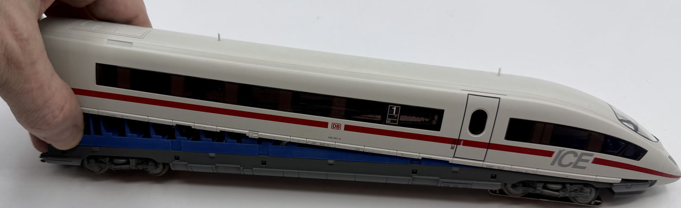
The coaches are not screwed together — neither the compartment coach, nor the driving trailer, nor the power car.
The body is held solely by latching lugs.
To open it, pull the body outwards a little at the bottom, carefully. Then start at one side of the coach and release the lower part from the upper body step by step. On the driving trailer the body has to be pulled off towards the rear.
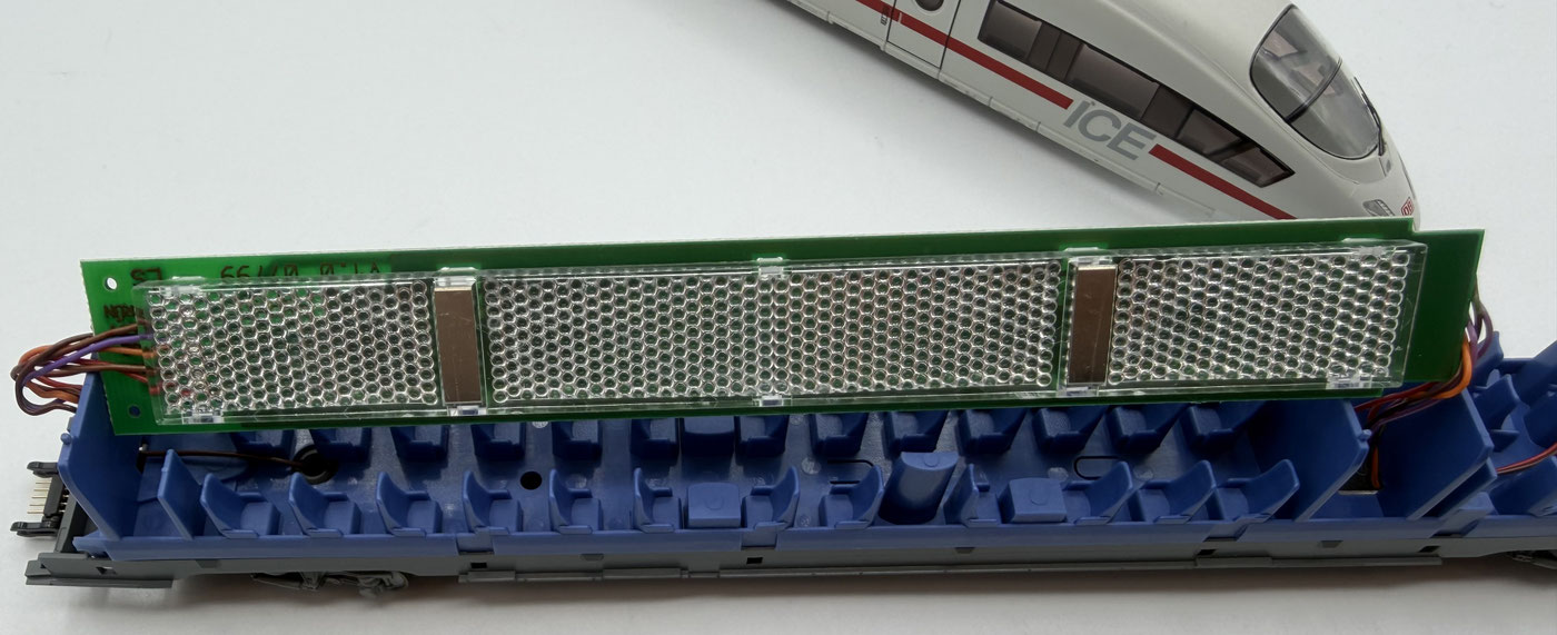
First the original board has to be removed. In our example it is still a board with filament bulbs. You can recognise it by the light guide mounted directly on the board. Your board may look somewhat different, but the basic principle is always the same.
As the first step we remove the light guide. It is merely clipped into the board and can be carefully released.
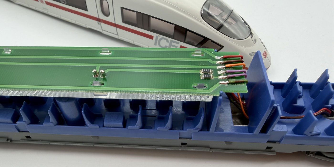
On the driving trailer the wires are soldered both on the top and, on the coupling side, underneath — directly beneath the light guide.
We start by unsoldering the wires on the top of the board one after another, and then release the wires on the coupling side of the old board beneath the light guide.
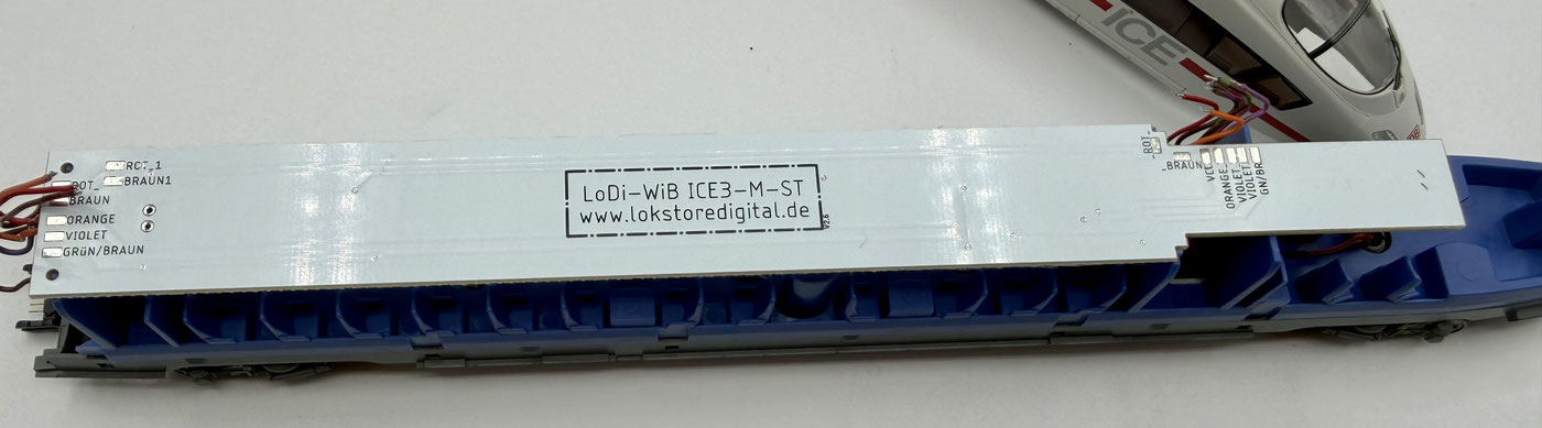
Now lay the LoDi-WiB ICE3-M-St into the coach. On our boards all the wires are soldered on the top. The board sits exactly in the coach, but can be fixed additionally with a small drop of superglue if needed.
The wires are then soldered to the board on both sides according to the given wire colours.
If the original front lighting is kept, either the brown-green or the brown-red wire is left unsoldered at the front end.
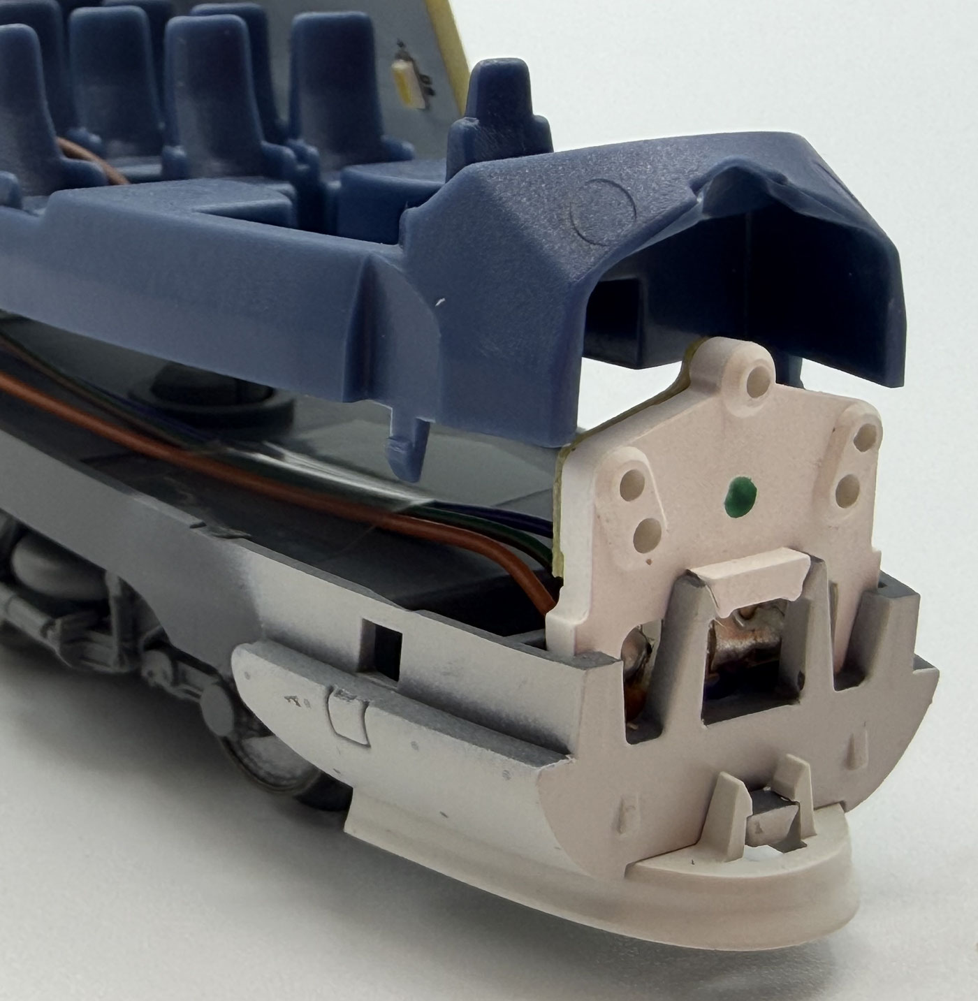
We also offer matching front lighting for the ICE 3 as a replacement. You will find it in our shop under "ICE 3 Märklin".
Fitting the front lighting is very simple and can be done straight away at this stage. To do that, first remove the old lighting. Open the seating unit at the front of the train as well as the lower part of the coach. The seats do not have to be taken out completely, since the old lighting is easy to reach and can be pulled out.
Depending on the version, two or three wires are soldered to the old lighting. In the normal version we do not use the high beam, since that channel is used for the interior lighting.
Connect the orange wire to VCC and the purple wire to red or white. There are two jumper bridges.
If you are using the original Märklin motor board, jumpers have to be set at JP1 and JP2.
The LoDi-Motor-WiB ICE2-M, by contrast, can be run to the DCC standard or through polarity reversal as used originally by Märklin. We still recommend using polarity reversal, that is closing jumpers JP1 and JP2. CAREFUL: the front lighting has no series resistors. Bear that in mind when connecting the board. If you use the LoDi conversion set for the ICE 3, the series resistors are directly on the driving trailer board.
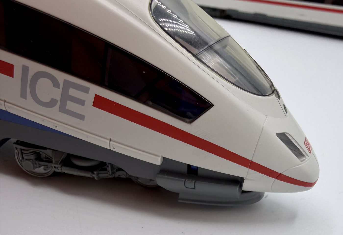
Once you have fitted the LoDi-WiB ICE3-M-St, the coach roof can be put back onto the driving trailer. Start by placing the roof at the end of the coach with the cab and then press it in carefully all round until it has latched fully.
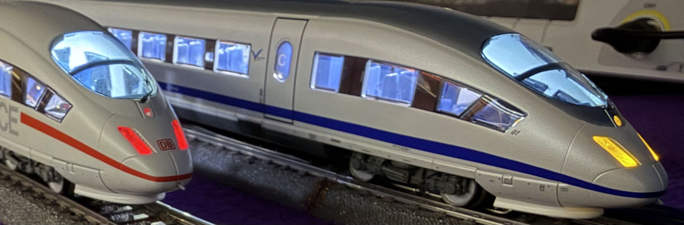
On the driving trailer the original front lighting is run through a polarity-reversing circuit. There are versions in which a high beam can be switched as well. That function is no longer available with our boards, since the control line needed for it is deliberately used for switching the interior lighting.
We will be offering front lighting of our own shortly. In keeping with the prototype, it will be fitted with warm white rather than yellow LEDs.

The compartment coaches, the LoDi-WiB ICE3-M
The compartment coaches are converted much like the driving trailer, and the conversion is done in a few steps. We proceed as follows:
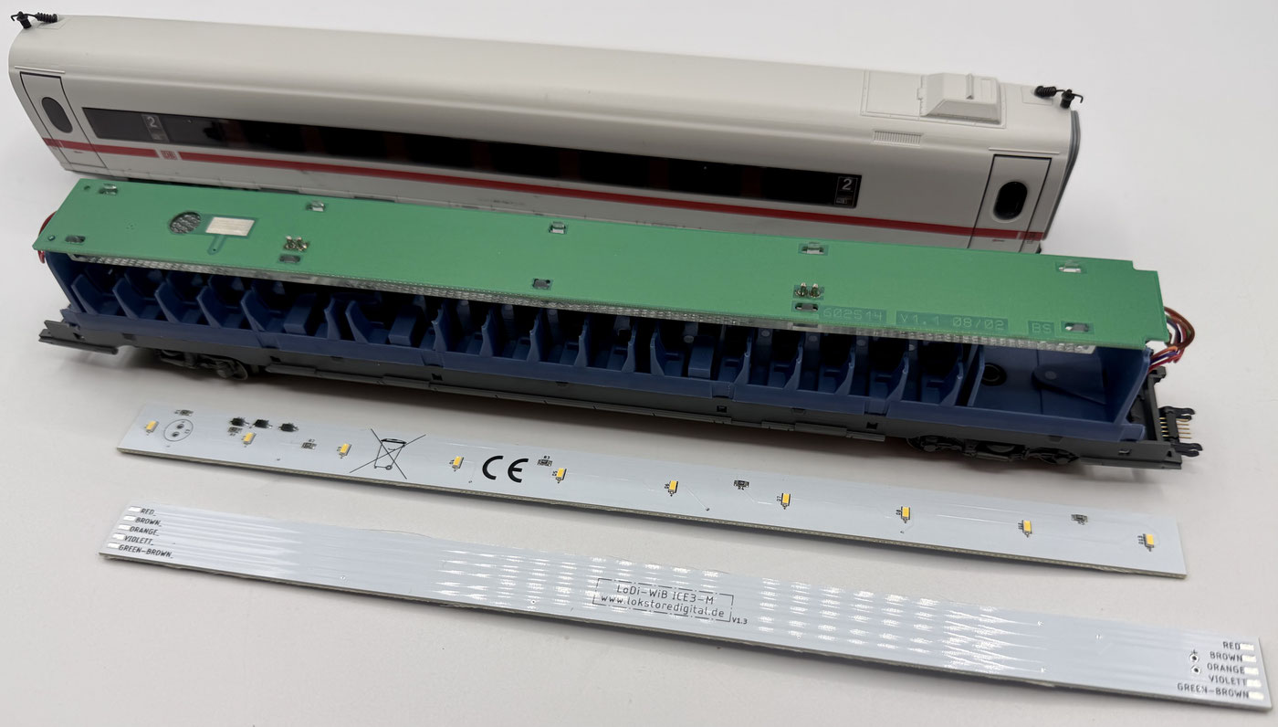
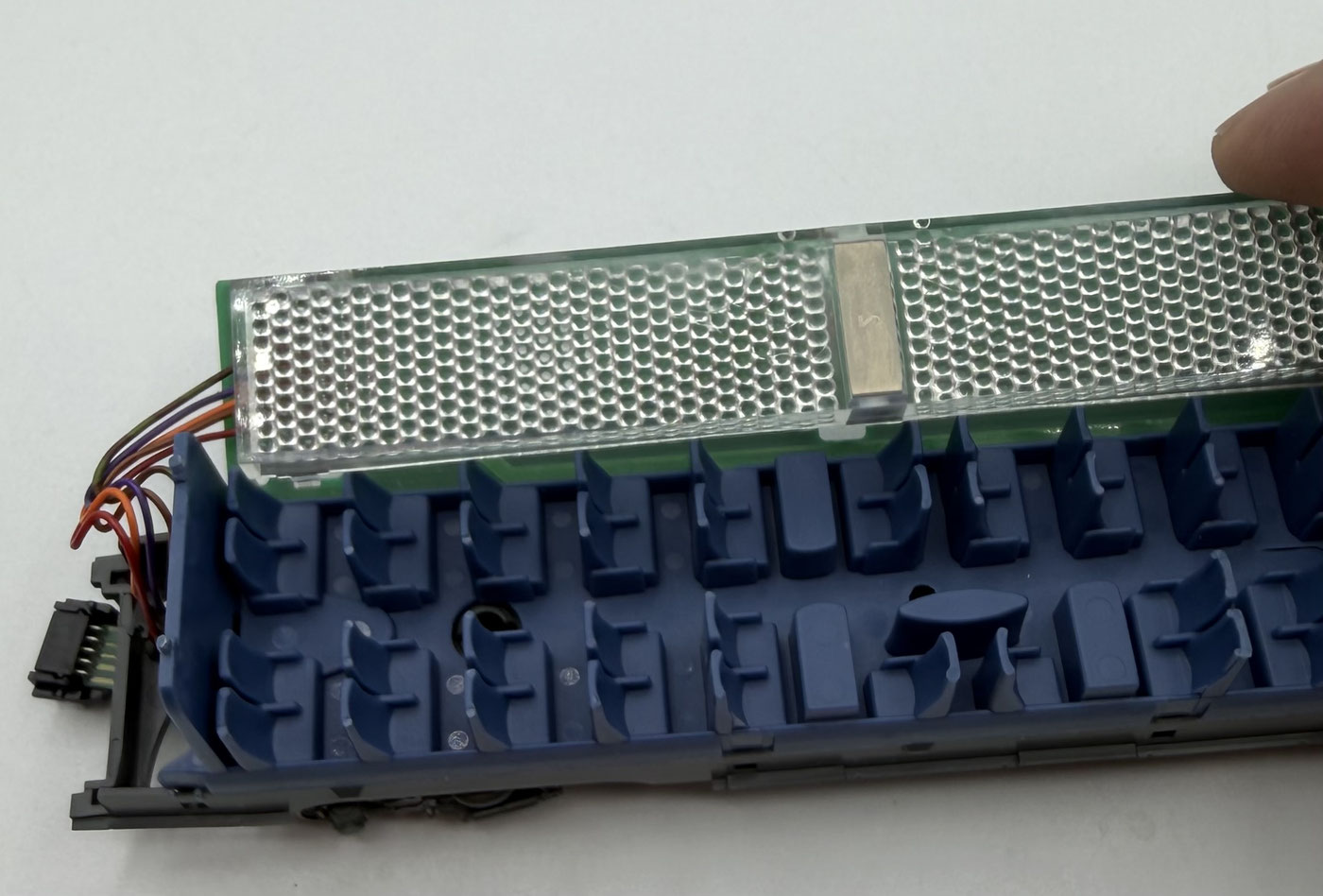
Remove the coach roof as on the driving trailer, by carefully easing the coach body apart a little at the bottom. Start at one side of the coach and release the lid step by step until the roof is completely separated from the coach.
Then remove the light guide from the board to get access to the wires and be able to unsolder them.

Now lay the LoDi-WiB ICE3-M into the coach. The board is somewhat narrower than the original version, but fits the existing holder exactly. If needed you can fix the board additionally with two small drops of superglue.
Then solder the wires back on. Observe the given wire colours. Depending on the train or coach, the green-brown wire may also be green-red or in another colour combination.
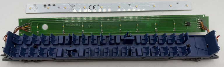
Some newer models of the coaches already have LEDs fitted from the factory. That lighting can of course be kept. Anyone wanting more uniform and harmonious illumination can nevertheless swap the original board for the LoDi-WiB ICE3M.
The conversion is the same as described above, except that there is no light guide here.
Fitting a buffer capacitor
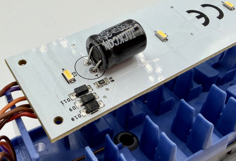
On the LoDi-WiB ICE-M(-St) there is a connection for a buffer capacitor, C1 or C2.
There you can connect a buffer capacitor from 100 µF at 25 or 35 volts. You will get the best result with a 330 µF 25-volt capacitor.
The LoDi-WiB ICE-M(-St) has a charging circuit for gentle charging. That way your booster does not go straight into a short circuit when switched on.
2. Installing the LoDi-Motor WiB ICE3-M(-S)
As mentioned already, Märklin make the ICE 3 in a great many different generations and designs. Fundamentally, though, the power car is relatively easy to convert on every version.
The only slightly greater effort is that the motor has to be taken out. Two suppression capacitors are connected directly at the motor, running from motor + and motor − to the locomotive body and thus to the track ground. These capacitors have to be removed, since they would otherwise impair the RailCom signal. In that case either RailCom information could be lost, or faulty signals would be sent back to the track.
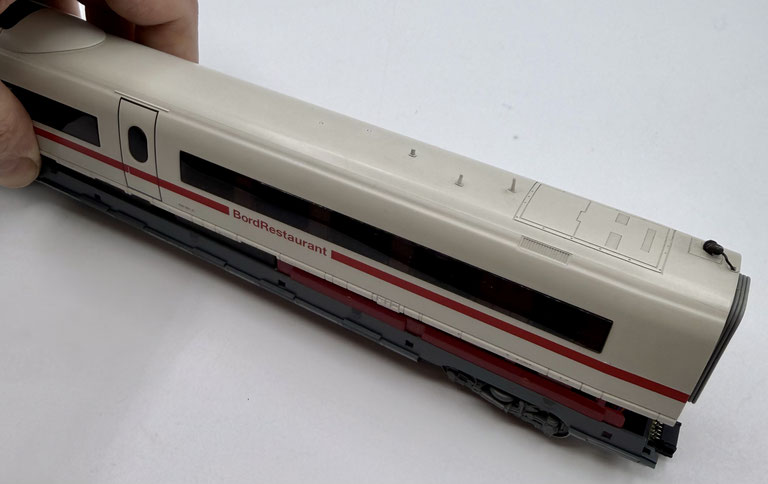
First we open the power car; like the other coaches it is bent apart a little from below and lifted out of the body from underneath.
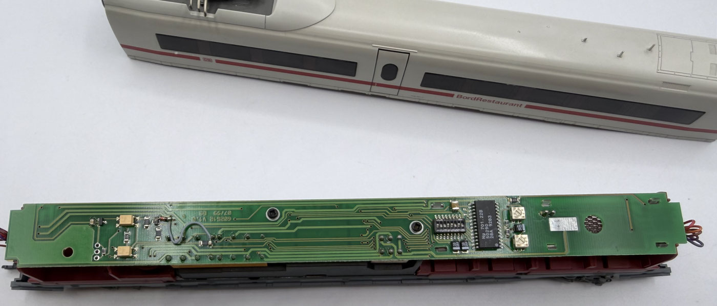
You should now see the large decoder board fitted originally (different on Trix, with an 8-pin interface).
This board is removed completely. It is fixed with two cross-head screws. Turn it over; on one side there is a light guide beneath which the wires are led into the board. Like on the other coaches, this light guide also has to be removed. Now unsolder all the wires from the board.
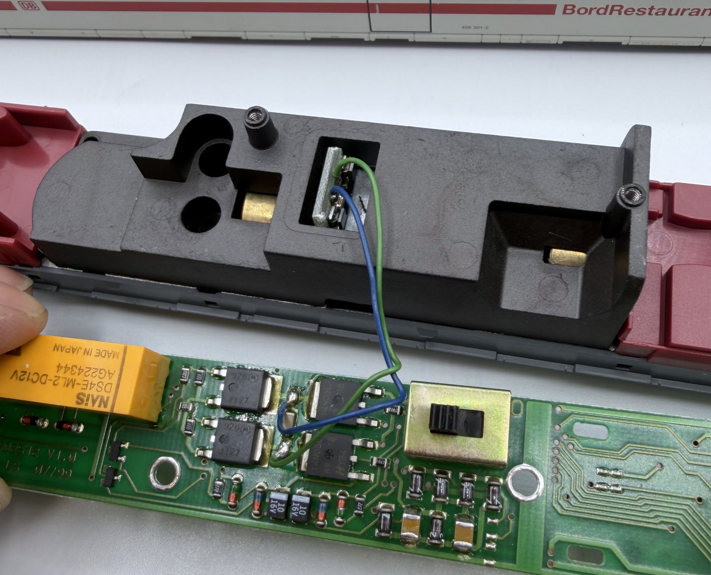
Underneath, the motor wires — the green and blue ones — are soldered to the original board. They now have to be removed from the board as well.
Converting the motor. Now we come to the slightly more demanding part of the conversion: the motor has to be taken out to get at the suppression capacitors.

To reach the motor, the plastic interior fittings first have to be taken out. That is easiest with a small screwdriver, with which the retaining lugs are pressed in carefully so the plastic part can be taken out.
Take care that the coupling then hangs free. There is a small spring there which can come loose easily and likes to disappear unnoticed, usually never to be found again 🙂
Once you have removed the body, 6 cross-head (Phillips) screws have to be undone.

After that the metal part can be taken out, revealing the motor beneath it. It merely lies loose in the frame and can now be carefully lifted out.
Take care that the cardan shafts to the bogies can slide out with it. They have to be threaded back in correctly later. In any case a function test should be carried out afterwards. If necessary, the cardan shafts can also be fitted back into the bogies from below.
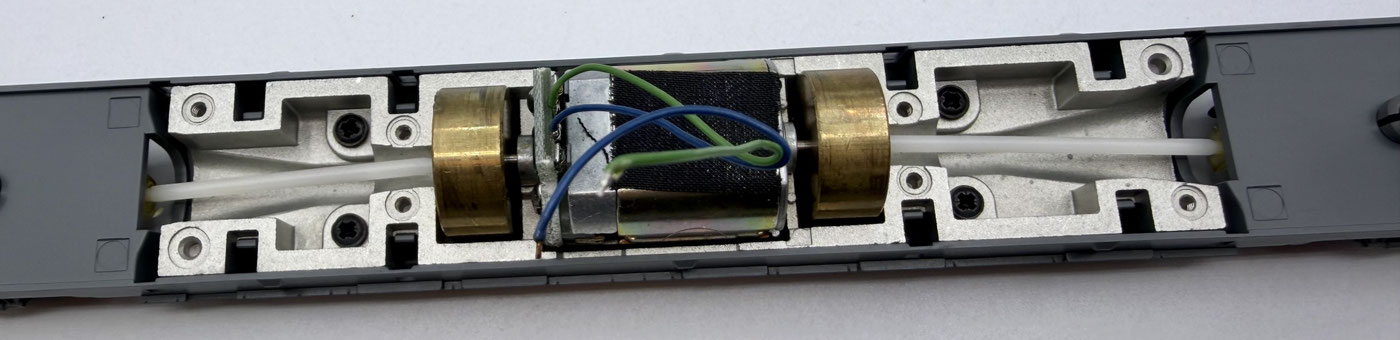
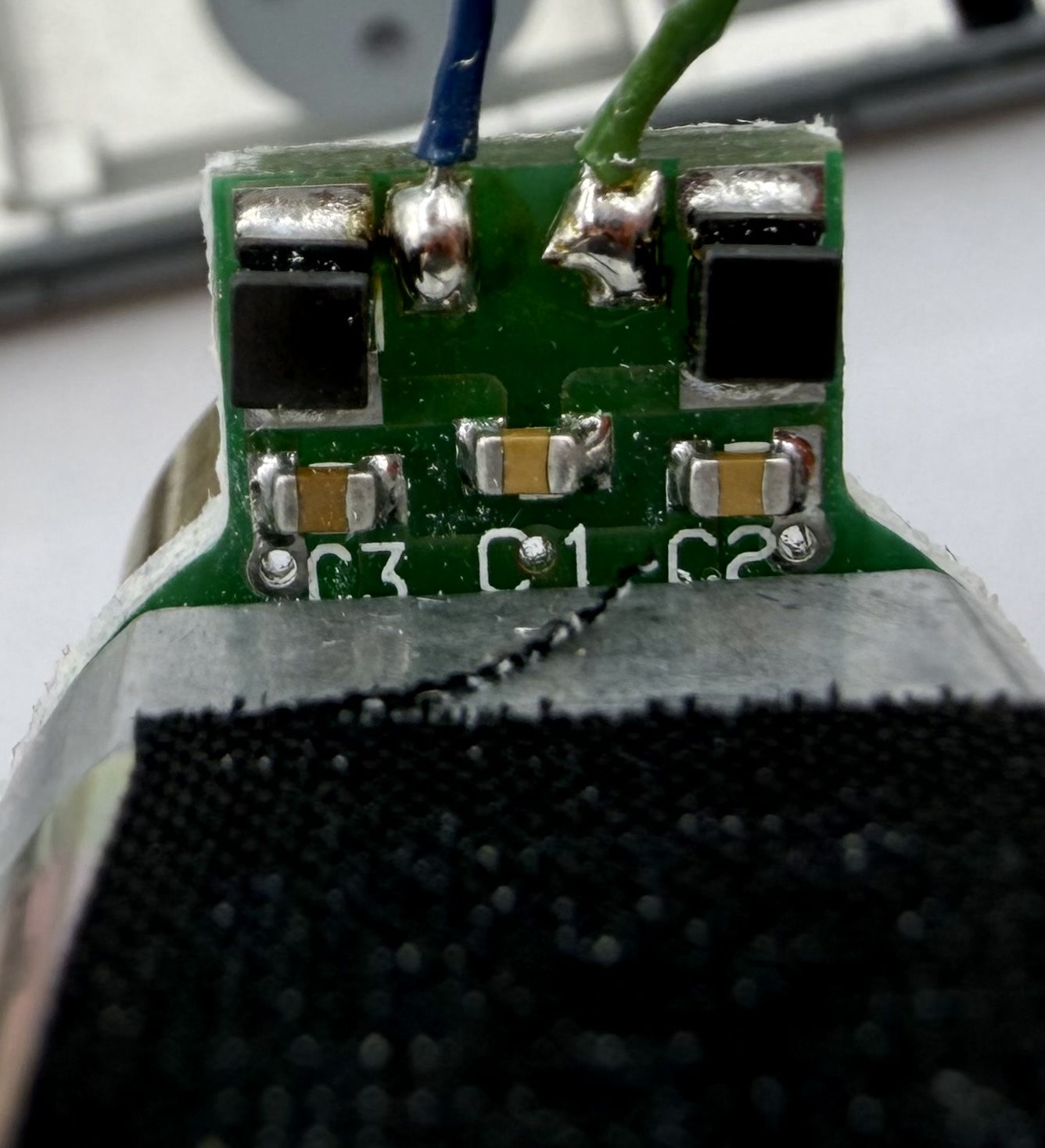
To isolate the motor from the track ground, the capacitors on the motor board have to be adjusted. There are three capacitors on the motor board in total. Of these, C2 and C3 have to be removed. C1 and the black chokes may stay on the board.
Once the capacitors are removed, the motor is put back into its holder and the cardan shafts reconnected. Then place the metal housing back onto the motor and screw it down with the six cross-head screws.
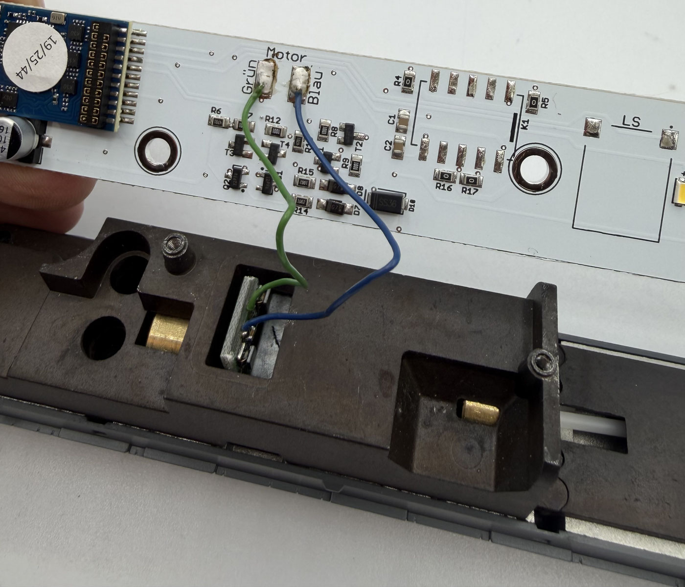
Now the LoDi-Motor WiB ICE3-M can be fitted. Start with the motor wires and solder them to the solder points marked for them.
The board only fits into the power car one way round. Like the original, it is later fixed with 2 cross-head screws.
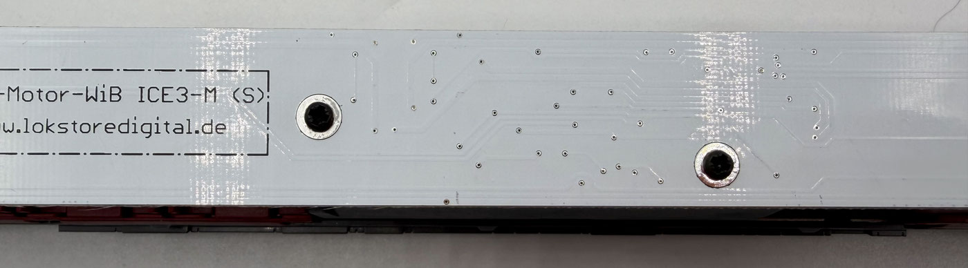
Once the board is fixed, the wires on the right and left sides can be connected as marked.
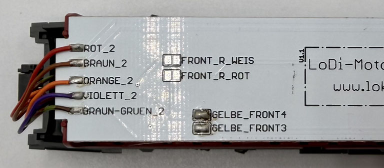
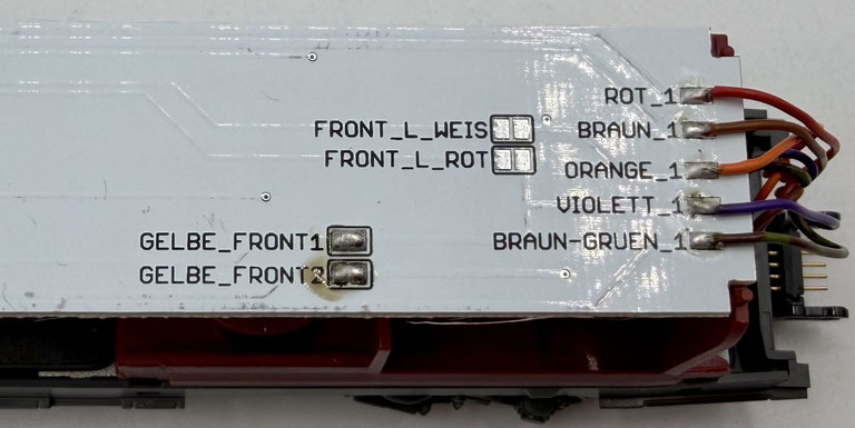

Now let us turn to the solder bridges. Depending on the front lighting fitted in the train, the matching solder bridge has to be set.
There is a simple way of telling which kind of front lighting is fitted in your ICE 3.
Yellow/red front lighting (1): if the front lighting of your ICE 3 is yellow/red, solder bridges Gelb_Front 1–4 have to be set on the board. (That is a polarity-reversing circuit as used in all older models up to about 2015.)
White/red front lighting (2): if the ICE 3 already has white/red front lighting, solder bridges Front_R_Weiß, Front_R_Rot, Front_L_Weiß and Front_L_Rot have to be set.
(Usually on newer trains, mostly with an mfx decoder.)
!!! CAREFUL !!!
Only the matching solder bridges may be set. On no account may all the solder bridges be set at the same time, as that will destroy the locomotive decoder.
!!! CAREFUL !!!
For our build we now use an ESU LokPilot 5; it has to be a decoder without amplified AUX 3 and 4, so not an MKL. The function mapping of the AUX outputs is as follows: F0 = red/white directional lighting, AUX 1 = pickup changeover position 1
AUX 2 = pickup changeover position 2
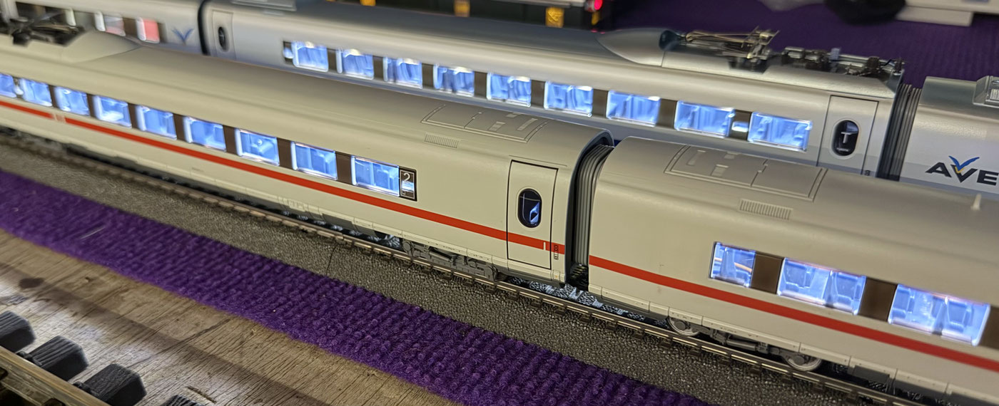
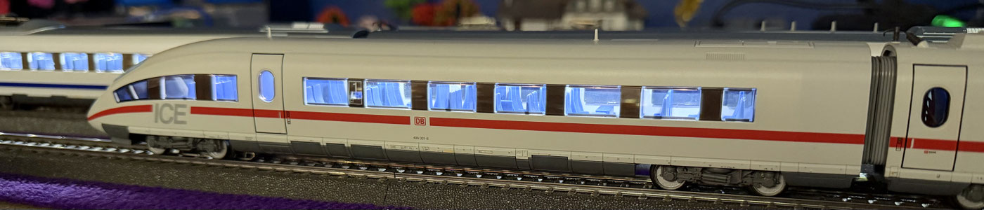
AUX 3 = output for the coach lighting, total load 1.5 amperes. AUX 4 = output for the on-board bistro light. The decoder can be programmed in the power car.
3. Technical data
Dimensions of the LoDi-WiB ICE3-M: length 242 mm, width 18 mm, thickness 1.55 mm. Weight: 16 grams. Suitable for digital and analogue AC operation.
From 7 to 24 volts.
Dimensions of the LoDi-WiB ICE3-M-St: length 215 mm, width 23 mm, thickness 1.55 mm. Weight: 18 grams. Suitable for digital and analogue AC operation.
From 7 to 24 volts.
Dimensions of the LoDi-(Motor) WiB ICE3-M-S: length 239 mm, width 23.5 mm, thickness 1.55 mm. Weight: 25 grams, or 27 grams for the (-S) version.
Suitable for digital operation.
From 7 to 24 volts.
The LoDi-Motor ICE3-M(-S) has a standard 21-pin MTC interface and can be fitted with all common locomotive or function decoders with a 21-pin interface.