
Hardware
LoDi-WiB ICE3-P
LoDi-(Motor) WiB ICE3-P
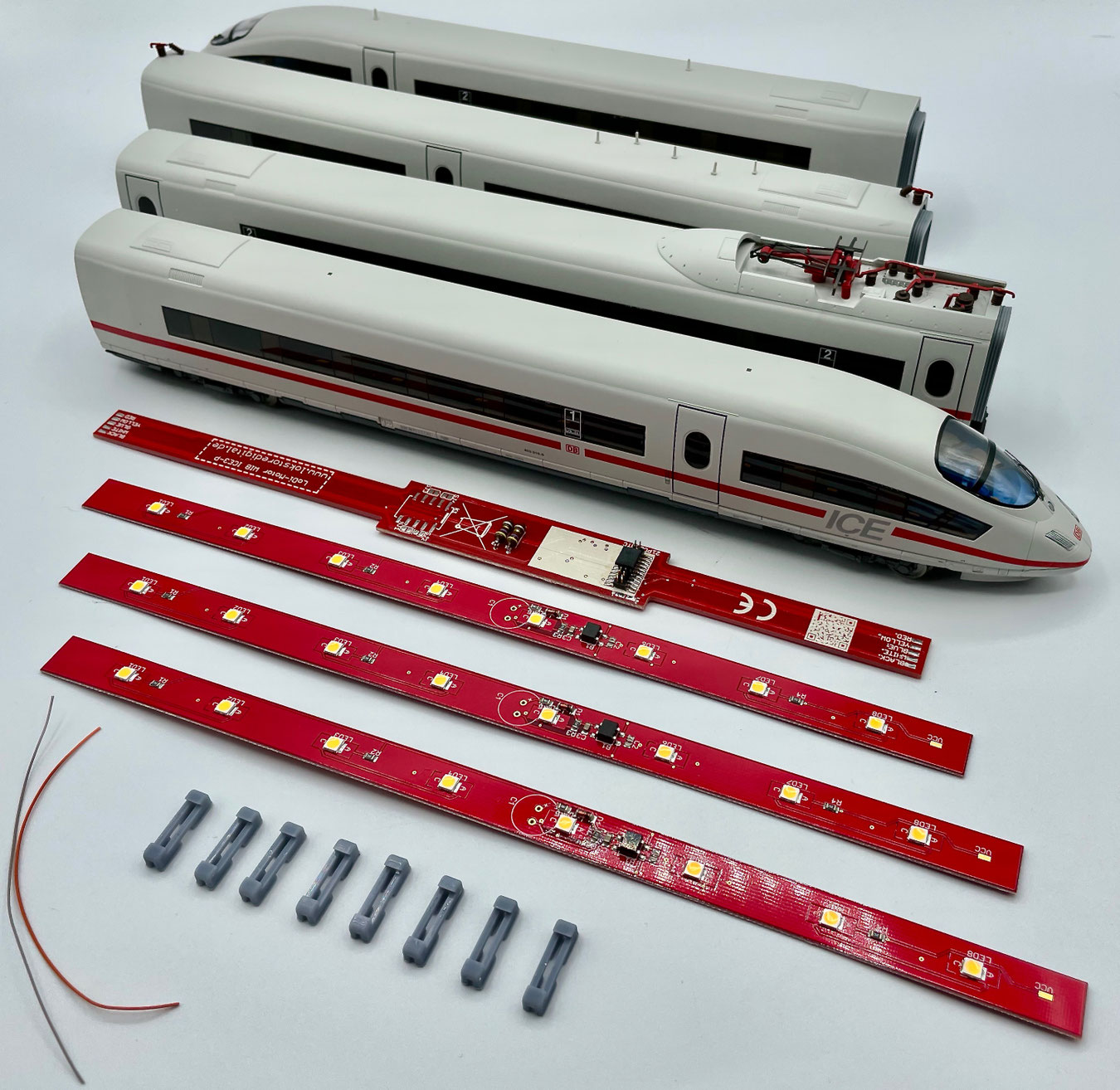
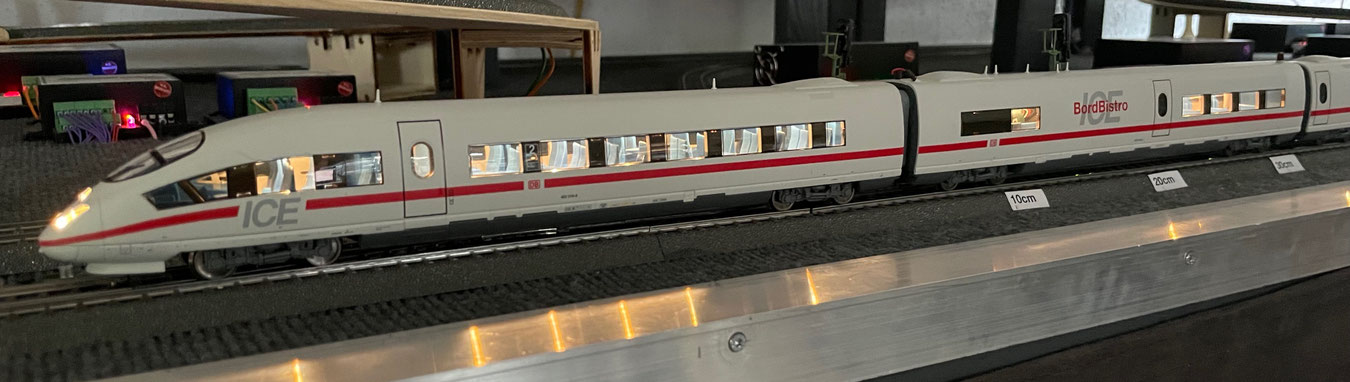
The ICE 3 is a truly impressive express train that delights younger model railwayers again and again. That is why we developed a board for this train that is very easy to fit.
With the power car board you have light in the power car as well.
It offers a 21-pin MTC interface and can therefore be fitted with any 21-pin decoder you like.
The train can be run fully on a RailCom®-controlled layout.
A changeover relay for the pickup changeover is provided for as an option, but is not needed on a computer-controlled model railway.
Features of the LoDi-WiB ICE3-P as well as the LoDi-Motor WiB ICE-3-P and -S
- Simple installation, optimised for vehicles with full RailCom capability.
- A precisely fitting design.
- The 21-pin MTC standard for connecting any decoder.
- Economical LED technology, perfectly lighting the PIKO® ICE 3.
An installation video from moba-tech
1. The LoDi-(Motor) WiB ICE3-P boards
In our shop you can choose between a complete set, individual LoDi-WiB ICE3-P boards for the compartment coaches, and the power car board LoDi-Motor WiB ICE3-P.
Compartment coach boards for the coaches as well as for the driving trailers.
Front and rear view.
You can enlarge the pictures by clicking.


CAREFUL!
On the compartment coach boards there are 2 solder jumpers on the top of the board. They are open as delivered! You have to decide on one of the operating modes, since otherwise the board will not light.
- SJ1 = continuous operation; it is not switched through the decoder.
- SJ2 = used if you are using the LoDi-Motor WiB ICE3-P or -S. Here the decoder's AUX 3 will switch the train's interior lighting. (Careful: AUX 3 must not be an amplified channel; it has to be a TTL, that is a logic, output.)

A power car board for the on-board restaurant.
Front and rear view.
You can enlarge the pictures by clicking.


2. Installing the LoDi-WiB ICE3-P set
If you can solder and have already lit one coach or another, the conversion should come easily to you. If you are a beginner, however, or do not feel up to a conversion, do get in touch with our partners.
They will be glad to make you an individual offer.
You can carry out the conversion yourself?
Then let us begin.
You will need:
- A soldering iron with a fine tip, and solder,
- a cross-head screwdriver and a pair of tweezers,
- a small, fine pair of side cutters as well as, if available, a wire stripper for fine cores,
- Superglue, to fix the boards lightly in place.
One more word before we begin... Piko® make the ICE 3 in various versions. We noticed that the starter set versions in particular only pick up current in one driving trailer, and that the wires for passing current on to the power car were not fitted either.
These wires can simply be retrofitted.
For our conversion here we assume the three-rail version, on which all the wires are fitted.
You can start the pictures as a small slideshow and enlarge them for a detailed view.
We will guide you step by step through a successful coach conversion with this description. If you notice while converting that steps or information are missing, do get in touch with us or visit our forum.
The compartment coaches. Let us start with the compartment coaches. For practised hands these should be convertible in less than 10 minutes. You need the LoDi-WiB ICE3-P for the conversion.
Always keep this in mind when converting!
If you are also gluing figures in and/or working with superglue to fix things, do not fit the coach roofs back onto the coaches straight away.
Superglue needs at least 1–2 hours to outgas completely.
Closing them too soon could otherwise lead to milky or tarnished glazing.
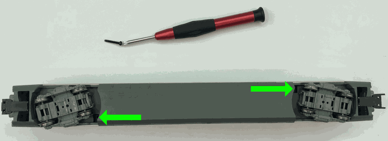
First unscrew the coach.
On the underside of the bogies there is a cross-head screw on the left and on the right (shown with the green arrow).
In the first step, remove these.
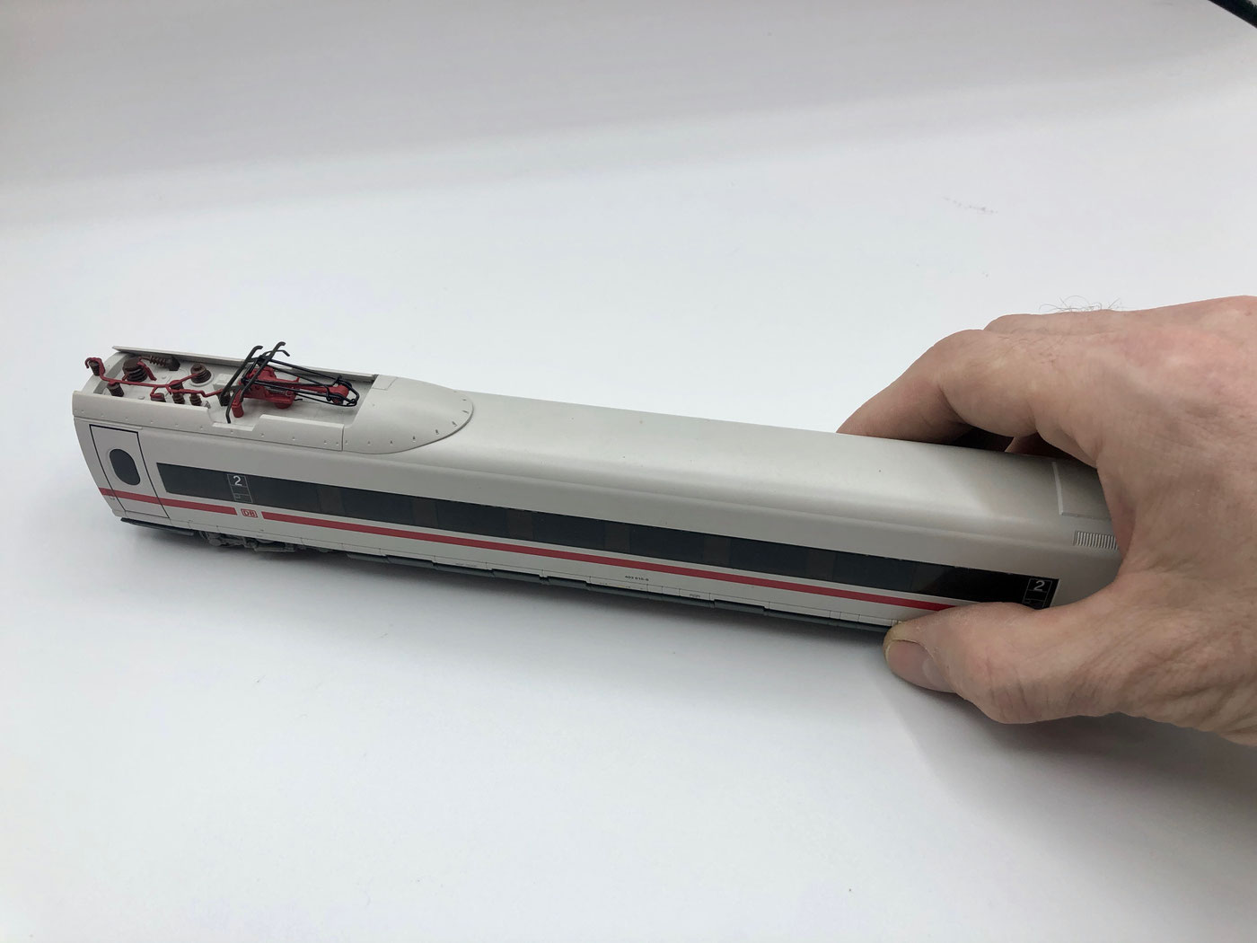
Turn the coach over and lift the roof off it. If it sticks a little, rock the roof carefully back and forth until the upper body comes free.
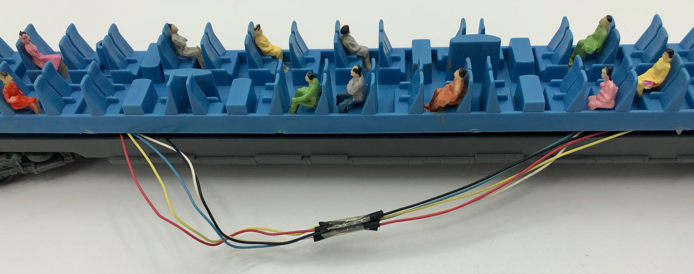
Five cores are carried from one side to the other through the current-carrying couplings.
You can now thread these out and cut them in the middle.
The current is carried from one side to the other across the board.
Thread all the wires back until they can be connected directly at the coupling.
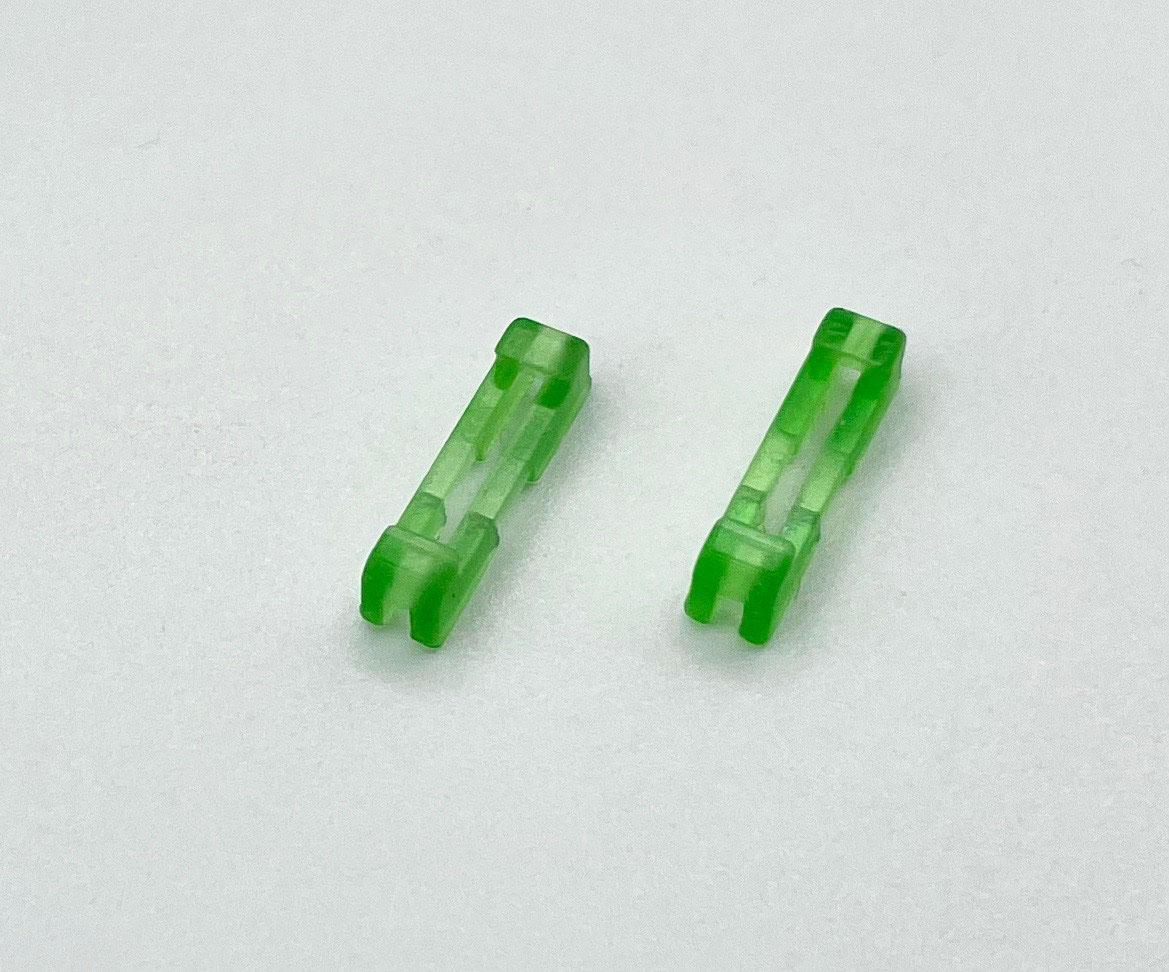
For easier handling we have developed dedicated holders for the boards. They can be fixed with a small drop of superglue if they should be too loose.
Take care that this holder does not fit at the point on the coach roof where a pantograph is installed.
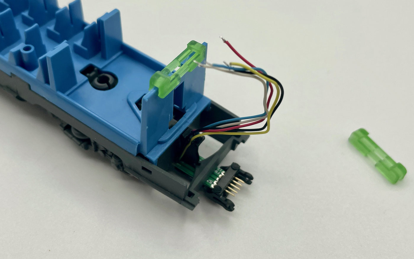
Shorten the wires to about 6 cm, measured from the coupling, twist them and tin the ends.
Now you can push the board's holder onto the coach and then clip the board into the holder.
Since this coach has a pantograph, we can only fit the retaining clip on one side here; a small drop of superglue on the other side gives sufficient fixing.
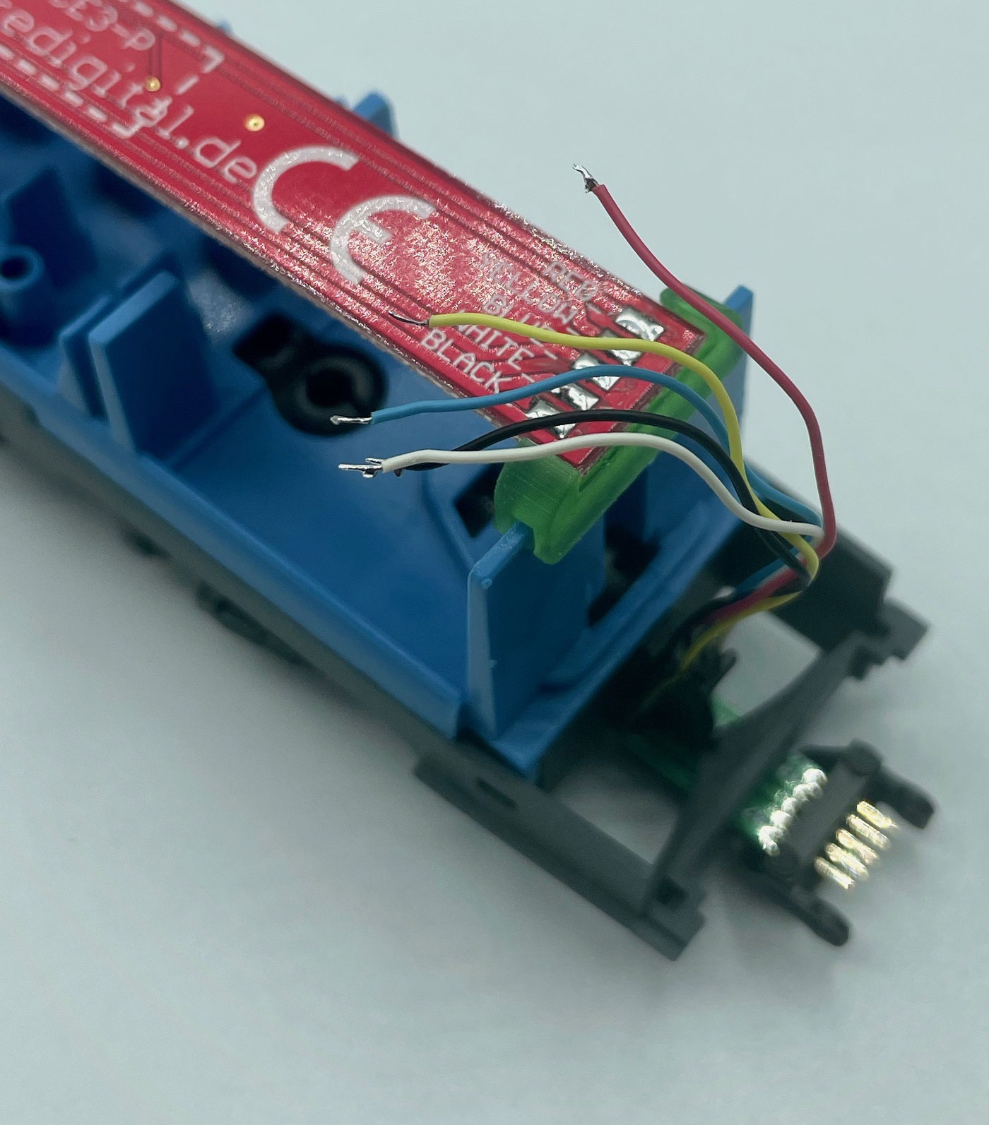
Now tin the board's pads with solder and solder the wires according to their colour, as printed on the board, on both sides of the coach.
After soldering, the wires are bent lengthwise over the board; that way they stay flexible with the coupling drawbar and do not break off at the solder point.
Now reassemble the coach.
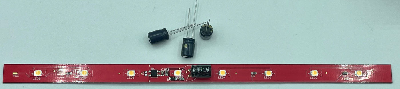
A buffer capacitor can be fitted to the LoDi-WiB ICE3-P for analogue or digital operation. The board already has the necessary charging electronics. In the middle of the board there are the solder connections for an electrolytic capacitor. Capacitors from 25 volts can be used; it should have at least 100 µF.
There is a + on the board.
WATCH THE POLARITY OF THE CAPACITOR!!!
To activate the capacitor in analogue mode, it is enough to close solder bridge SJ1; the board will then light continuously, in analogue as well as digital mode.
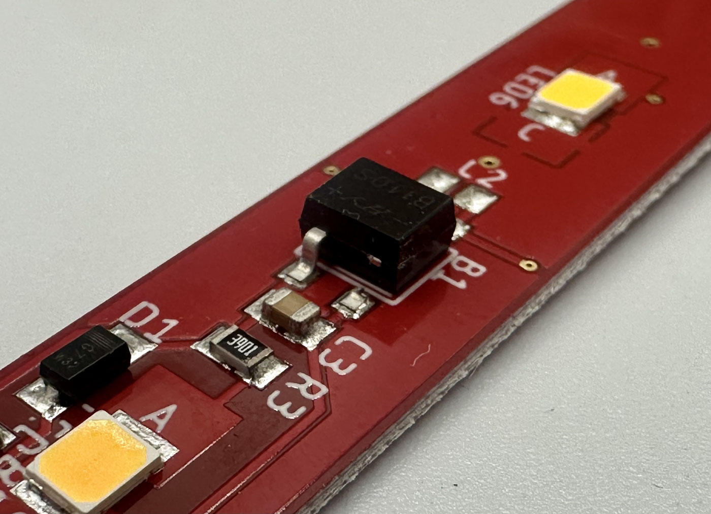
If you want to switch through the decoder in the power car and fit a capacitor, both solder bridges, SJ1 and SJ2, have to be closed. The negative pole at the rectifier also has to be cut.
Look at the board more closely: at capacitor C3 the rectifier's negative pole runs towards the lettering. Here you can cut the negative pole with small side cutters. Switching then happens through the decoder ground, and the capacitor can be charged.
The on-board bistro (power car)
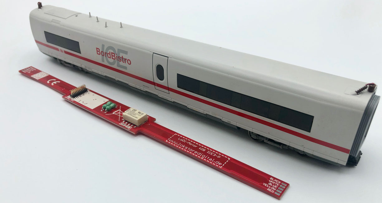
In the on-board bistro, where the motor is fitted, we will now install the LoDi-Motor WiB ICE3-P.
The power car we show can differ from the one in your train, since various versions of this power car were built. You need the LoDi-WiB Motor ICE3-P (-S) for the conversion.
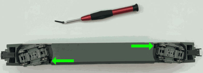
The power car has 2 cross-head screws at the same place as the compartment coach, which you first have to undo. After that the roof can be taken off in the same way as on the compartment coach.
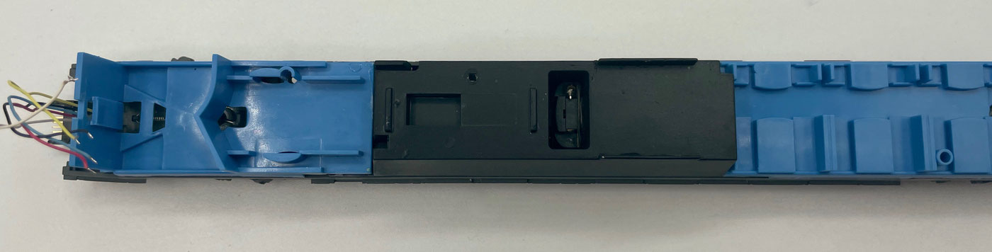
Now remove the boards inside the power car. The capacitors and chokes fitted also all have to be removed.
Check this carefully and make sure both terminals at the motor are clear and no other components are connected to them.
The wires are shortened to about 6 cm from the coupling, the same length as on the compartment coach, and unsoldered.
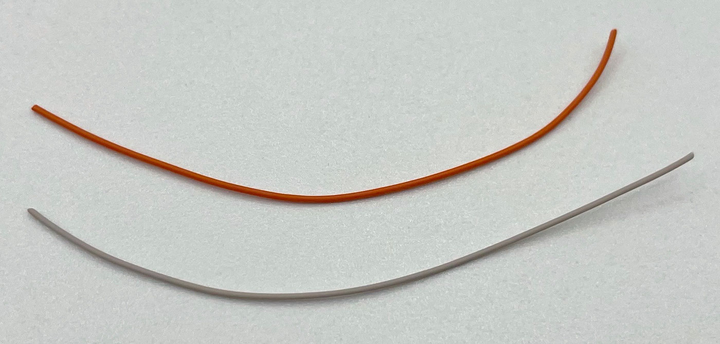
Two connecting wires are supplied with the power car board in the large set. You first have to solder them to the board.
After that you can connect the motor with the wires.
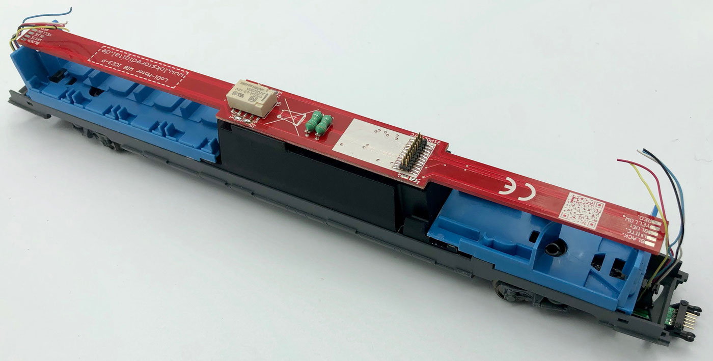
Now fit the board holders supplied and clip the boards into them. If one should be loose, you can fix it with a small drop of superglue.
Now solder the pads on the board and solder the wire to the matching colour marking on the board.
Finally, bend the wires over in the same way as in the compartment coach.
Now plug a decoder of your choice onto the 21-pin MTC interface.
Now reassemble the power car in the reverse order to the way you took it apart.
If you want to fit a sound decoder in your ICE 3, you can connect a loudspeaker directly to the LoDi-Motor WiB ICE3-P.
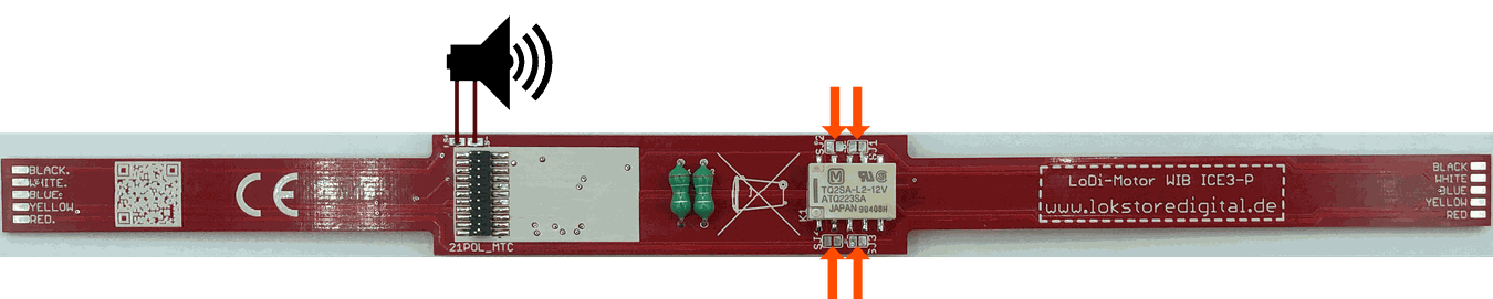
If you ordered a pickup changeover as well, you can switch it off with 4 solder bridges that you can set on the board. With these bridges the pickup changeover is disabled.
Now fit a decoder of your choice onto the motor board. In our tests we use an ESU LokPilot 5, but you are welcome to use sound decoders or decoders from other manufacturers. Take care, though, that the decoder does not have an amplified AUX 3, or that it can be switched to TTL, that is to a logic output.
F0 = white at the front, red at the rear. AUX 1 and 2 = driving the relay for the pickup changeover. AUX 3 = coach light on/off. The following 21-pin decoders have been tested: ESU LokPilot 5 multi-protocol / 59619
ESU LokPilot 5 DCC / 59629
ESU LokSound 5 / 58419
Märklin mSD and mLD decoders. Using other decoders? No problem — do let us know which decoder you run the board with and we will add it to the list :)
The driving trailers
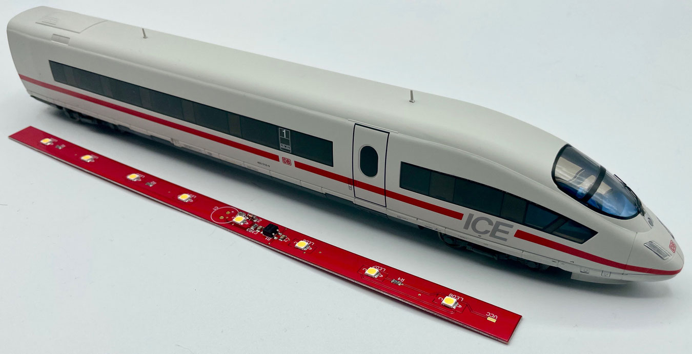
The two driving heads of the Piko® ICE 3 are converted very quickly and easily. See which steps are needed.
You need the LoDi-WiB ICE3-P for the conversion.
The driving trailer we show can differ from the one in your train, since various versions of this train were built.
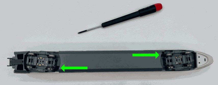
Like all the other coaches in the ICE 3 series, the driving trailer too has 2 cross-head screws at the points marked with green arrows, which you first have to undo. The roof cannot however be lifted off as easily as on the other coaches.
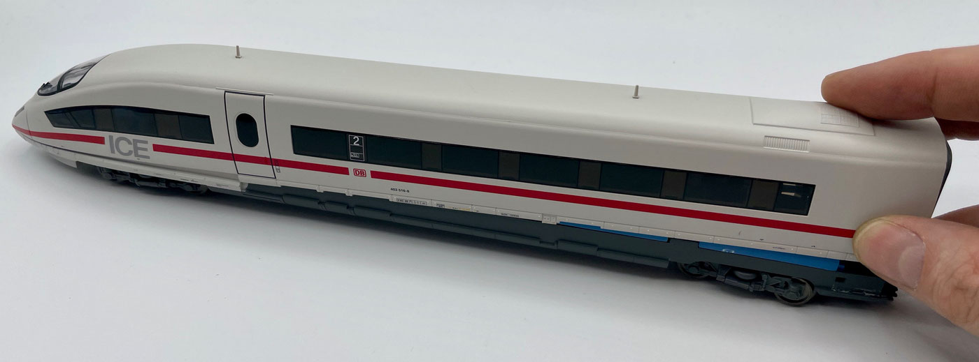
When taking the coach roof off, first lift it upwards at the rear of the coach. You will now notice that the whole thing jams at the front part of the coach. Those are the light guides. The roof simply has to be pushed forwards and away now.
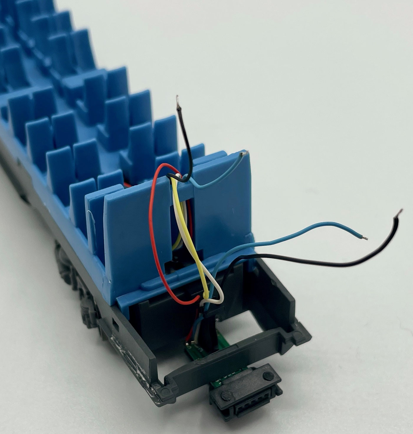
Now that we have lifted the body off, we turn to the coupling end of the ICE 3 coach. There, pull the blue and black wires out about 1 cm. Now cut the wires so that enough slack is left between the coupling and the WiB.
Next we fit the spacers supplied with the set. The first is fitted at the end where the coupling is. You can lay the wires through the notch in the holder, as shown in the picture. The second holder is pushed in further forward.
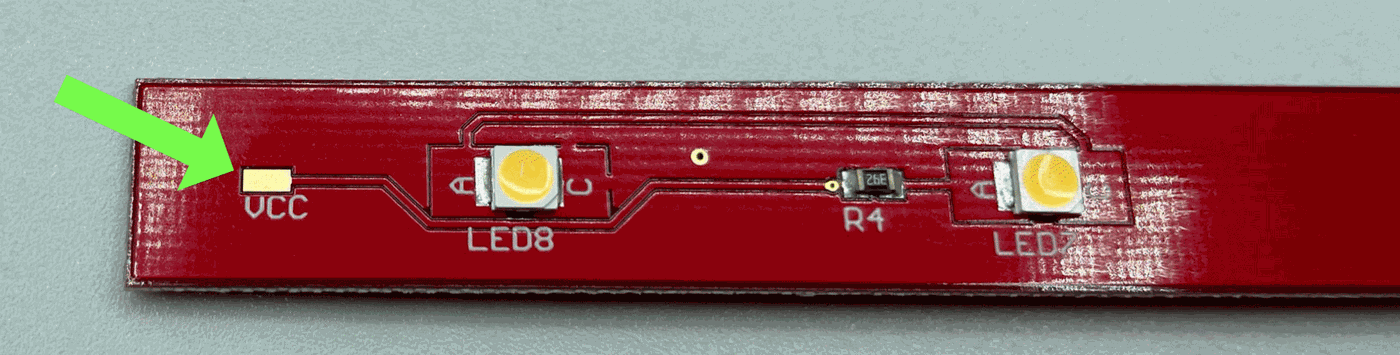
On the underside of the board there is a further solder point, the VCC connection. It is used so that the directional lighting can be switched through the decoder. First connect the blue wire coming from the coach to VCC, as seen in the picture.
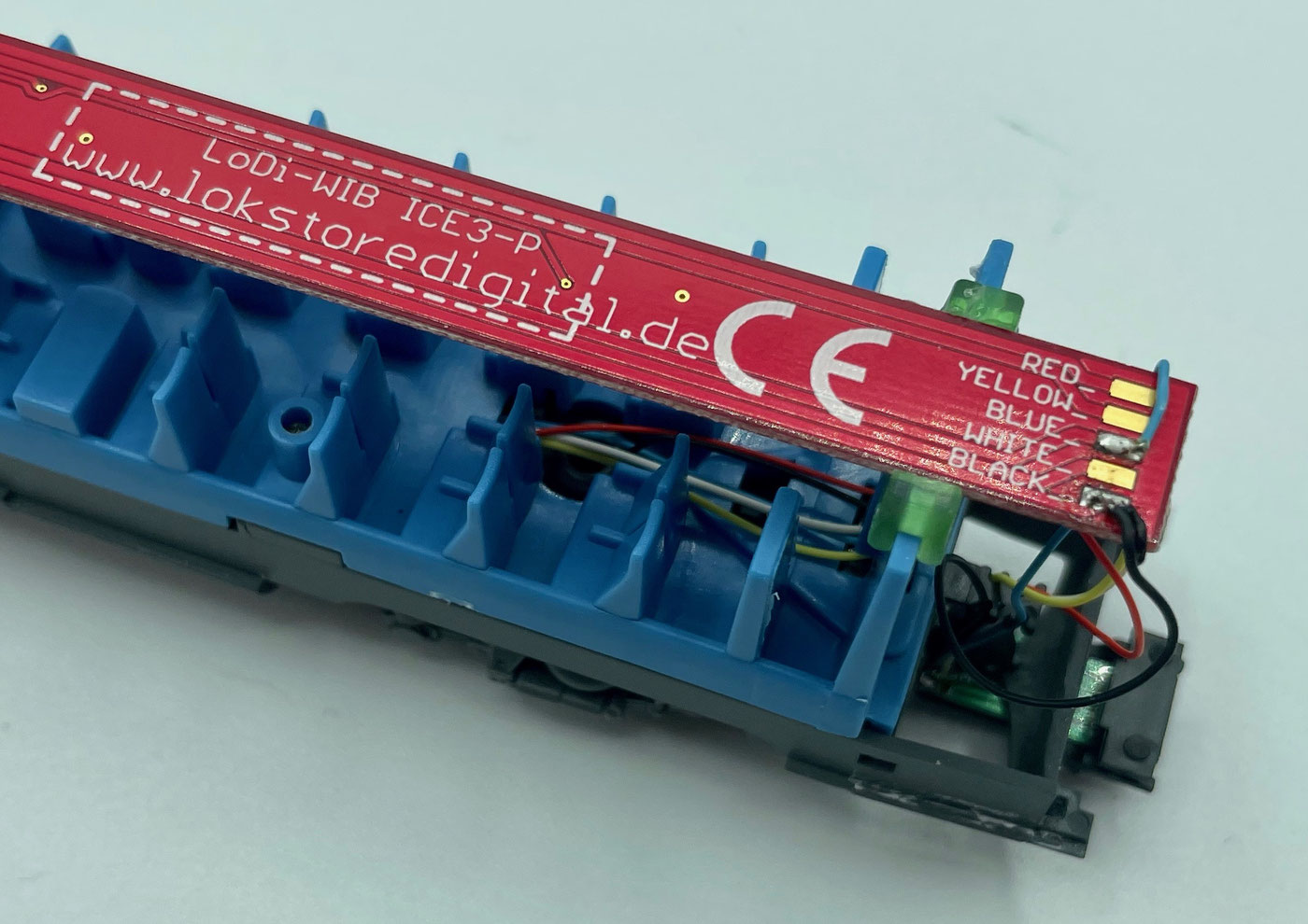
As the next step, solder the blue wire coming from the coupling to the Blue pad on top of the board, and the two black wires to the Black pad, as seen in the picture.
Please do not fix the board with glue.
If you use the mfx or Motorola data format on your command station, flickering can occur in the train. In that case the red wire also has to be connected to the board in the driving trailers (that is, the right-hand wheel pickup or the centre-rail pickup).
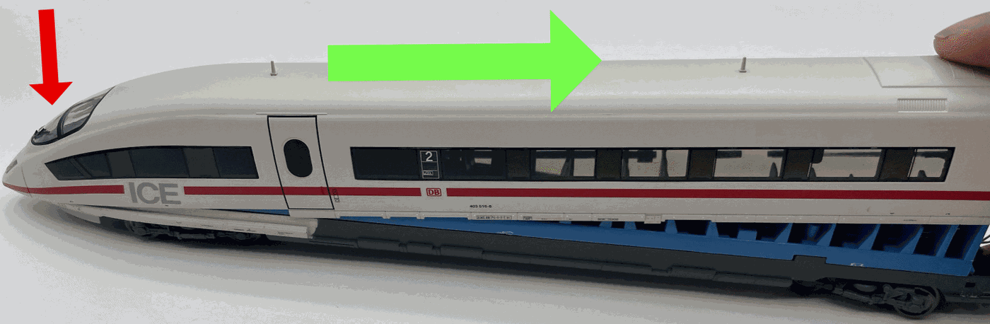
When reassembling the train the board has to be able to slide, since we have to push the light guides back in as we did when taking it apart. The board therefore has to be able to move inside the coach.
When reassembling, the front part of the coach first has to be threaded downwards into the light guide (see the red arrow). After that the coach roof can be pushed onto the coach.
3. Technical data
Dimensions of the LoDi-WiB ICE3-P: length 240 mm, width 12 mm, thickness 0.7 mm. Weight: 8 grams. Dimensions of the LoDi-(Motor) WiB ICE3-P: length 244 mm, width 12 mm, or 20 mm at its widest point.
Thickness 0.7 mm. Weight: 13 grams, or 15 grams for the (-S) version.
The LoDi-Motor ICE3-P (-S) has a standard 21-pin MTC interface and can be fitted with all common locomotive or function decoders with a 21-pin interface.

Would you like to see the quality of the devices for yourself?
Visit our forum, where experienced users are glad to help.