
Hardware
LoDi-Booster
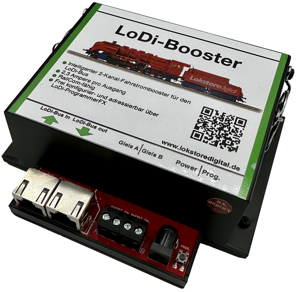
Your vehicles need power!
Depending on how large your layout is, enough current has to be provided. Not only that — ideally you should also have some short-circuit logic, so that a single short does not take the whole layout down.
We have many years of experience with these amplifiers in small layouts, large layouts and show layouts, and can now present our LoDi-Booster.
A dual booster with an adjustable power supply included!
In a class of its own — and RailCom capable above all!
Features of the LoDi-Booster
- It supplies the current needed to run the digitally controlled locomotives and the turnouts, as well as every other consumer on the layout.
- In the event of a short circuit on the layout (caused by a derailed coach or locomotive, for instance) the booster cuts the power to the layout to prevent further damage to the rails or the rolling stock.
- Thanks to the built-in intelligence of the LoDi-Booster, only the affected sections are switched off in the event of a short, and this is reported back to the control software in use. The rest of the layout can keep running without risk of damage to the rolling stock.
- The booster brings the voltage to the track so that the digital driving and switching commands reach every vehicle and accessory decoder on the layout.
- The LoDi-Booster has two channels, each providing 2.3 A. If you need more, you have to connect a corresponding number of further LoDi-Boosters to secure the supply.
- On layouts monitored with RailCom, the LoDi-Booster provides the RailCom cutout, which carries the RailCom return channel.
- A dual booster with 2.3 amperes per track output. The outputs can be bridged, which makes 5 amperes available.
- The current is easy to set through the LoDi-ProgrammerFX and the LoDi-Con.
1. The LoDi-Booster and its connections
The LoDi-Booster works with the LoDi bus (formerly µCon bus). You need the LoDi-Rektor as the booster command station. It is a full command station, but through a CDE input it can also work as a booster station. Conventional command stations can then be connected without trouble.
The booster has the following connections:
- (1) Programming button: every booster has its own address through which it is addressed on the bus. To set a new address the button has to be pressed first. The address is then assigned through commissioning software such as the LoDi-ProgrammerFX or the LoDi-Con.
- (2,3) LoDi bus input: the LoDi bus is fed into this socket. LoDi bus OUT: further LoDi or µCon components connect here. The output supplies power for the LoDi-CV-Programmer and the TrainSpeed.
- (4,5) Track outputs A and B: the track outputs can carry 2.3 A continuously and 2.8 A peak.
- (6) Connection for the supplied power supply: (please use only the supplied power supply! Lokstoredigital accepts no liability for damage caused by other power supplies, and the warranty is void in that case.)
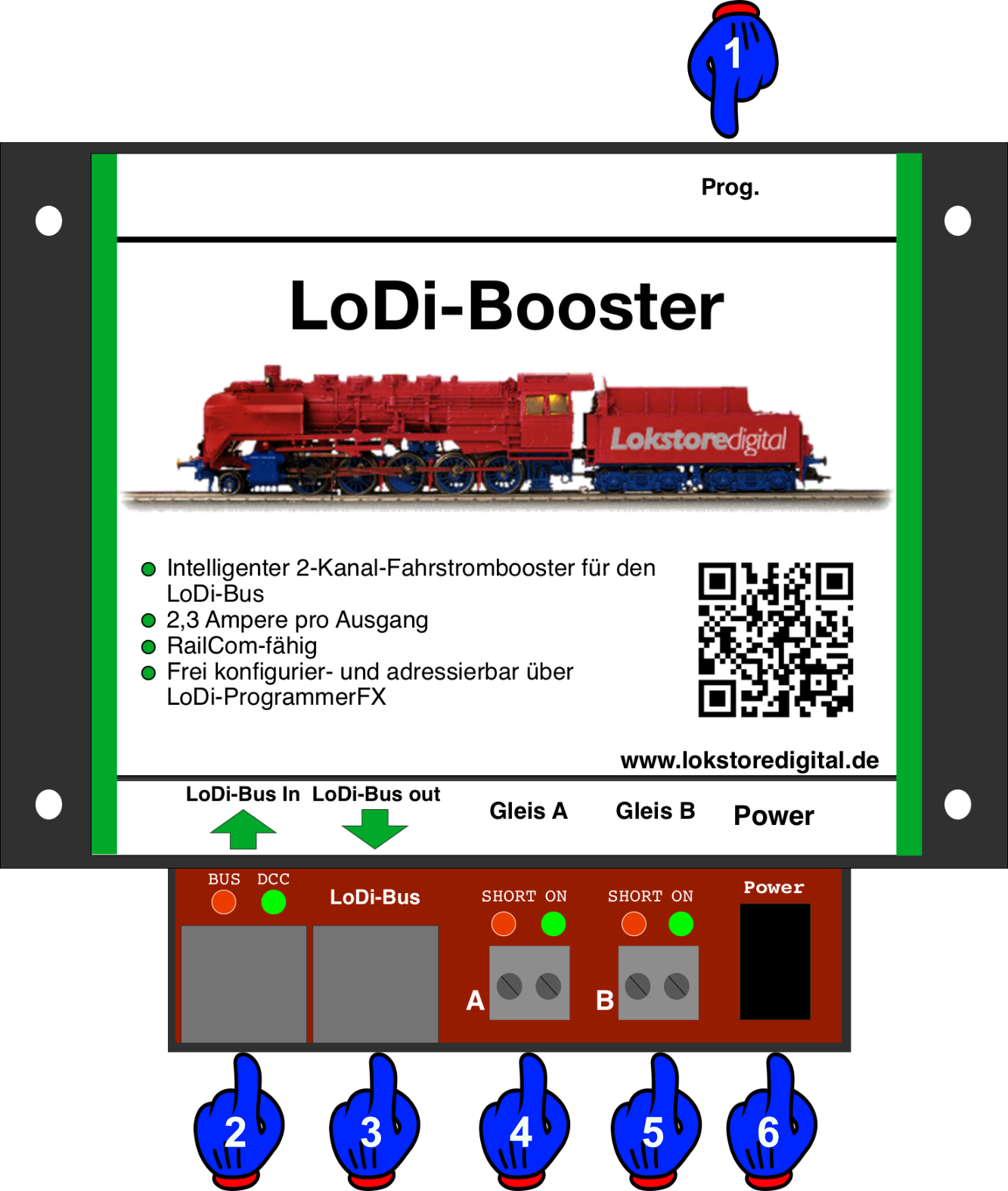
The LoDi-Booster received a small hardware update in September 2024. The track output terminals were merged to give more stability. The "Prog" button was also moved to the front.
2. LEDs and programming button of the LoDi-Booster
The LED indicators on the LoDi-Booster give you information that helps with troubleshooting and with setting the device up.
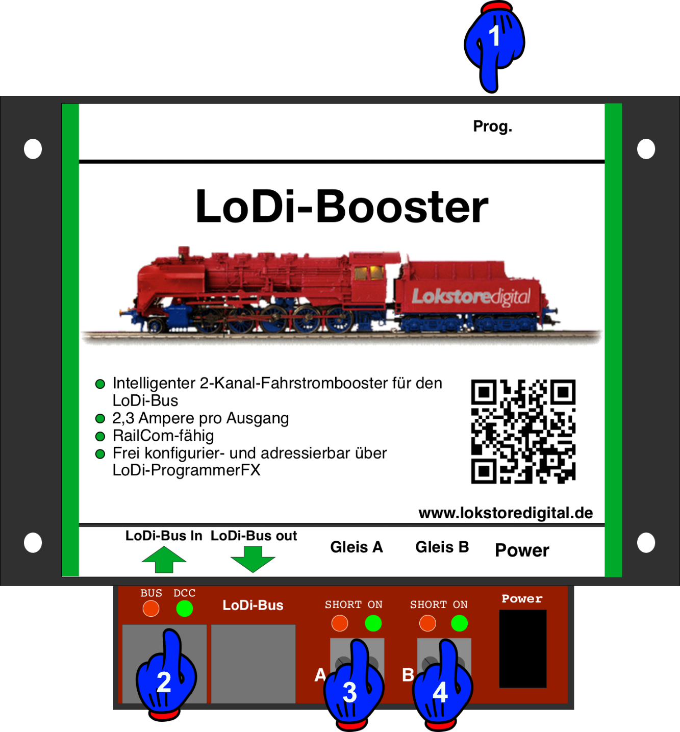
- BUS LED = shows the state of the LoDi bus. When the bus signal is detected, the LED lights with a short pulsing interruption.
- DCC LED = this LED is lit continuously as soon as the booster receives a signal over the bus — DCC, Motorola or M3 alike. If no bus cable is plugged in, or the LoDi-Rektor is switched off, the DCC LED flashes rapidly.
- Short on track A and B = this LED indicates a short circuit at the booster output. As soon as a short is detected, the LED starts to flash.
- On for track A and B = as soon as this LED is lit at the respective output, the output stage in the booster is active, meaning power is present at that output.
- Prog. button = there is a prog. button on the booster. It switches the booster, or rather its output stages, on and off.
A short tap of the button switches the track outputs off and on again. The ON LED for track A and B goes out or lights up accordingly.
The prog. button is also used to programme the address. The LoDi bus provides 63 addresses. Held for more than 3 seconds, the bus and DCC LEDs flash red and green alternately. This can be interrupted by pressing the button again, or it ends when a new address is sent to the booster over the bus. Once the booster understands the signal, programming ends and it returns to normal operation.
3. The fan on the LoDi-Booster
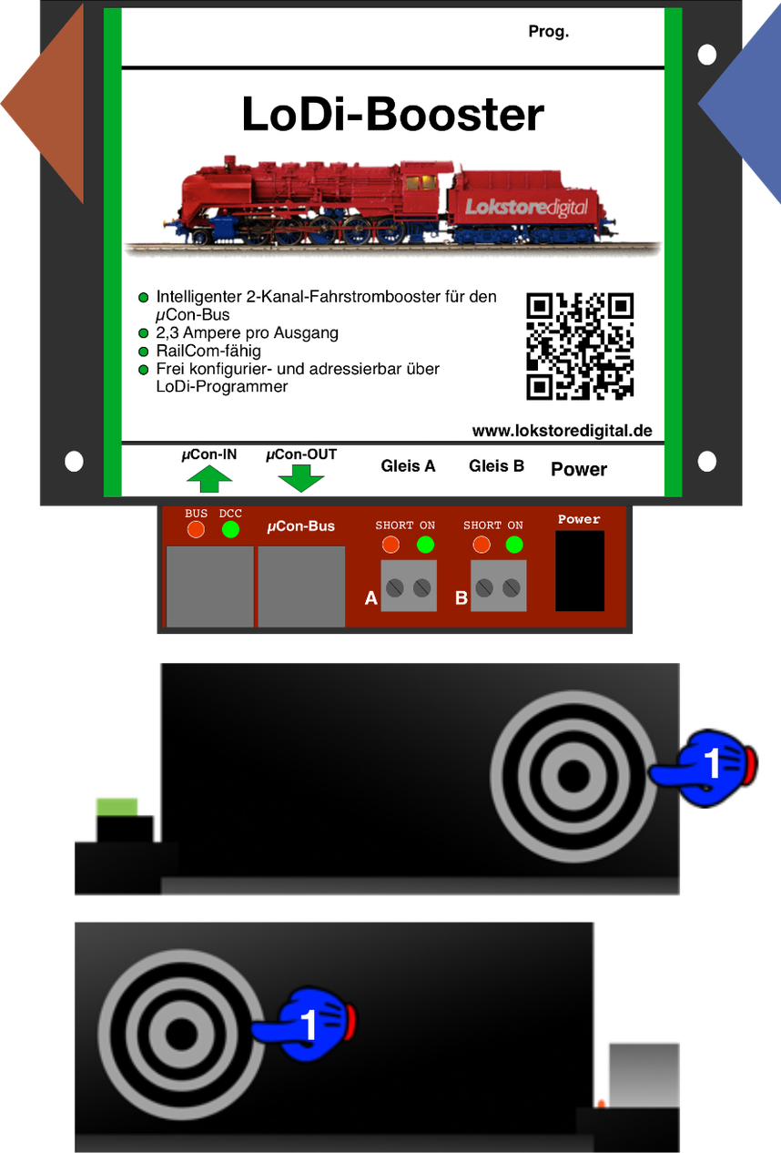
The LoDi-Booster has a built-in fan. This fan is controlled by temperature and load. As soon as the temperature inside the device rises, or current is drawn at the output, the fan automatically speeds up and slows down.
The fan never stops entirely; it keeps turning at low speed even when idle.
Please make sure that no objects get inside the device through the slots. Screws and the like could cause an internal short circuit and destroy the device.
The ventilation grille protects against the spinning fan.
The booster should be mounted so that the warm air can flow through it. Allow enough space for the air coming in and going out; 5 cm of clearance on each side is enough.
The air is pushed through the device from right to left.
4. Connecting a power supply
Update 9/2024.
From now on the LoDi-Booster is delivered with a high-quality ESU power supply. We took this step because we are thoroughly convinced of the quality of the ESU units. The voltage is set comfortably with a potentiometer, which makes the supply suitable for every scale. This power supply was tested specifically for use with the LoDi-Booster.
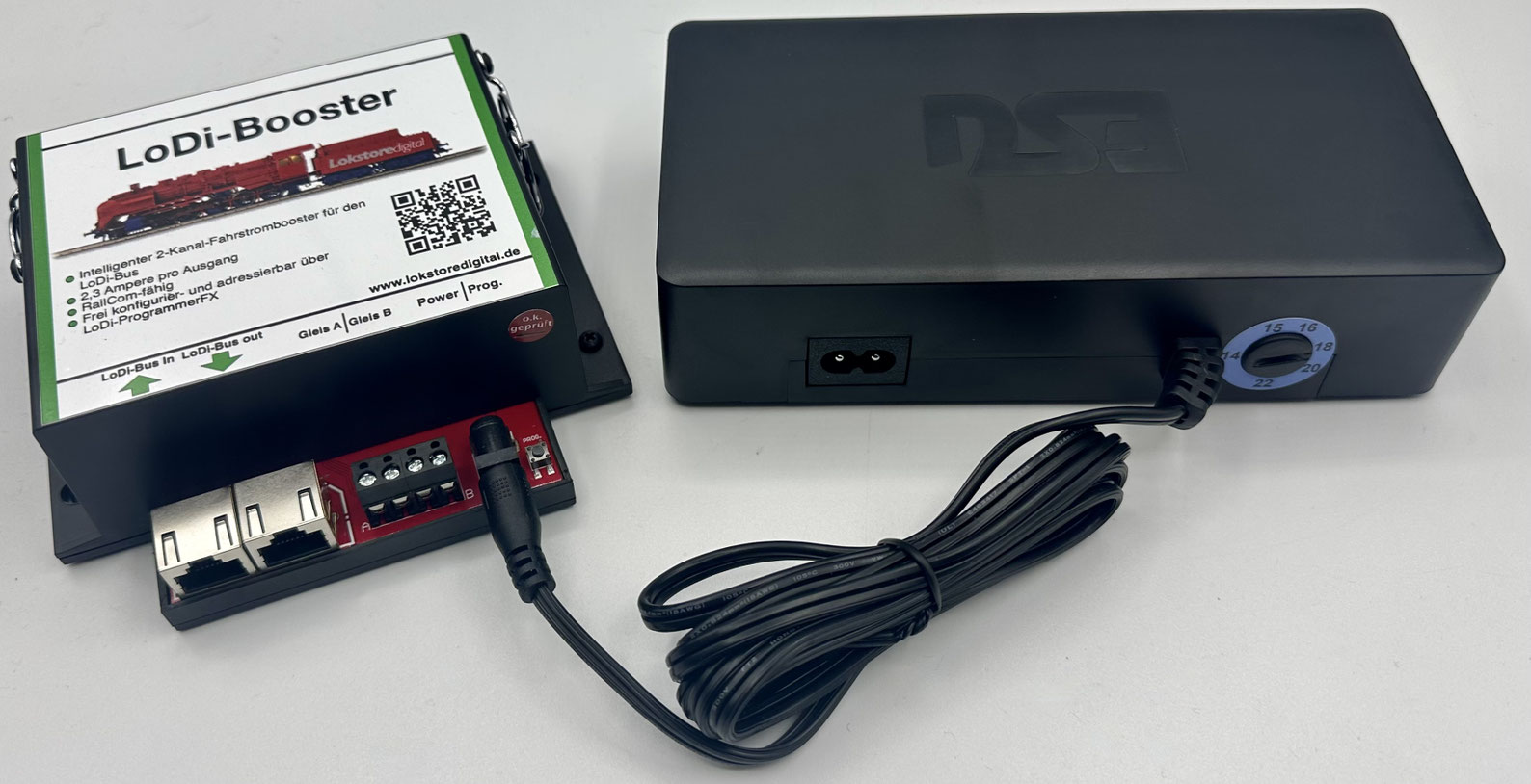
The voltage is very easy to set on the power supply. There is a rotary potentiometer at the power output which you can adjust comfortably with a finger or, say, a coin.
To trim the voltage precisely, you can call up the voltage of the booster in question in the LoDi-ProgrammerFX and set the booster to your scale.
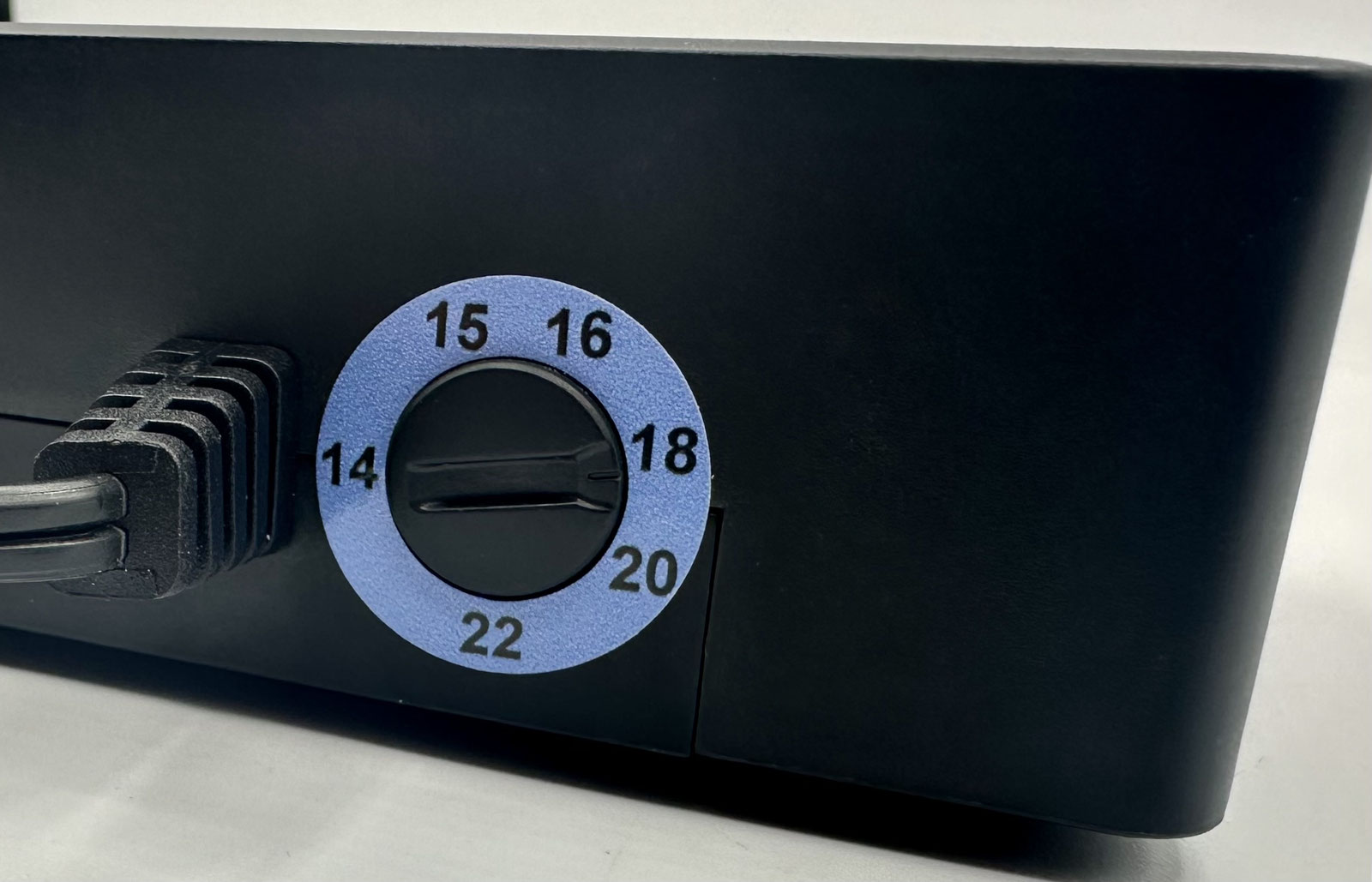
Please note: do not use other power supplies of unknown origin.
Improper use of power supplies can damage the electronics.
A mains cable is included in the delivery as well.
The power supplies are available in the following voltages: 22 volts = for gauge 1, G
20 volts = for gauge 1, G, 0, H0 two-rail and three-rail. 15 volts = for H0 two-rail, H0m, H0e, TT, N
14 volts = for scales smaller than N
At the stated voltage the power supply provides the following current: 7 amperes
5. Connecting to the LoDi bus
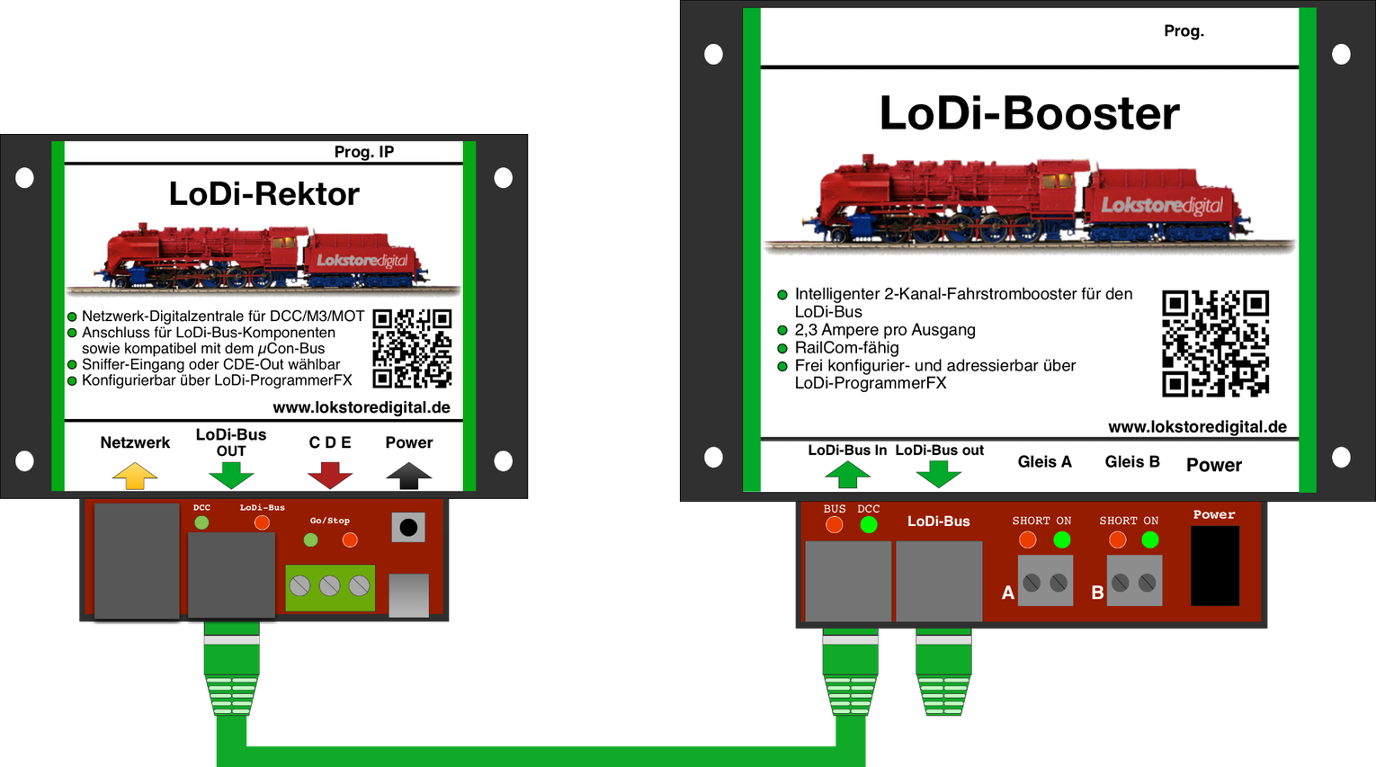
The LoDi bus (formerly µCon bus) is a bus developed specifically for boosters, to cover long distances without losing the data signal.
The bus is open and can be downloaded straight from our website by developers.
Devices on the LoDi bus have to be plugged in one after another; the bus does not allow for a star topology.
The following example shows how the booster is supplied with information by the LoDi-Rektor.
In this case the LoDi-Rektor provides the data for the booster and sends it over the LoDi bus.
Beyond that, the booster can also deliver data to the LoDi-Rektor and thus to the LoDi-ProgrammerFX or the control software.
That data can include current measurement per channel, voltage measurement, short on A and B, and device temperatures.
Besides the various short-circuit sensitivities, the address can also be set on the booster through the LoDi-Rektor with the LoDi-ProgrammerFX.
The RailCom cutout can be switched off on the LoDi-Booster. You will find more on that in the LoDi-ProgrammerFX section.
6. Connecting old µCon system components
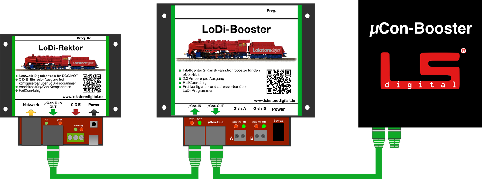
The LoDi bus is fully compatible with the µCon bus by LSdigital. µCon components such as the Railspeed or a µCon booster can be integrated anywhere in an existing LoDi bus without trouble.
Please note, however: although both systems are compatible on the bus, mixing LoDi boosters and µCon boosters on the same track section is not recommended. With RailCom enabled on the LoDi-Booster in particular, interference with RailCom communication can occur.
For trouble-free operation it is advisable to supply track sections either entirely with LoDi boosters or entirely with µCon boosters. Older µCon boosters can, for instance, continue to supply DCC accessory decoders or a separate part of the layout.
7. Connecting to the three-rail system
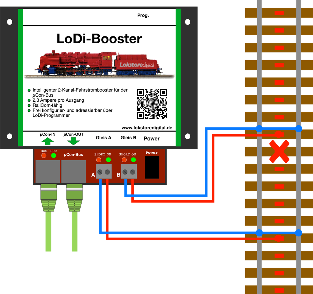
On three-rail layouts the track commons are not separated from one another. That is no problem for the LoDi-Booster; all commons may be joined.
In this picture you see the common brought together through the track. It makes no difference whether you run a common bus wire or join the commons only through the track.
In the example only the centre rail is separated.
Please always watch for sufficient cable cross-section, and for enough feed points on the layout.
No cable below 0.75 mm² should be used; the maximum cross-section for the screw terminals is 1.5 mm².
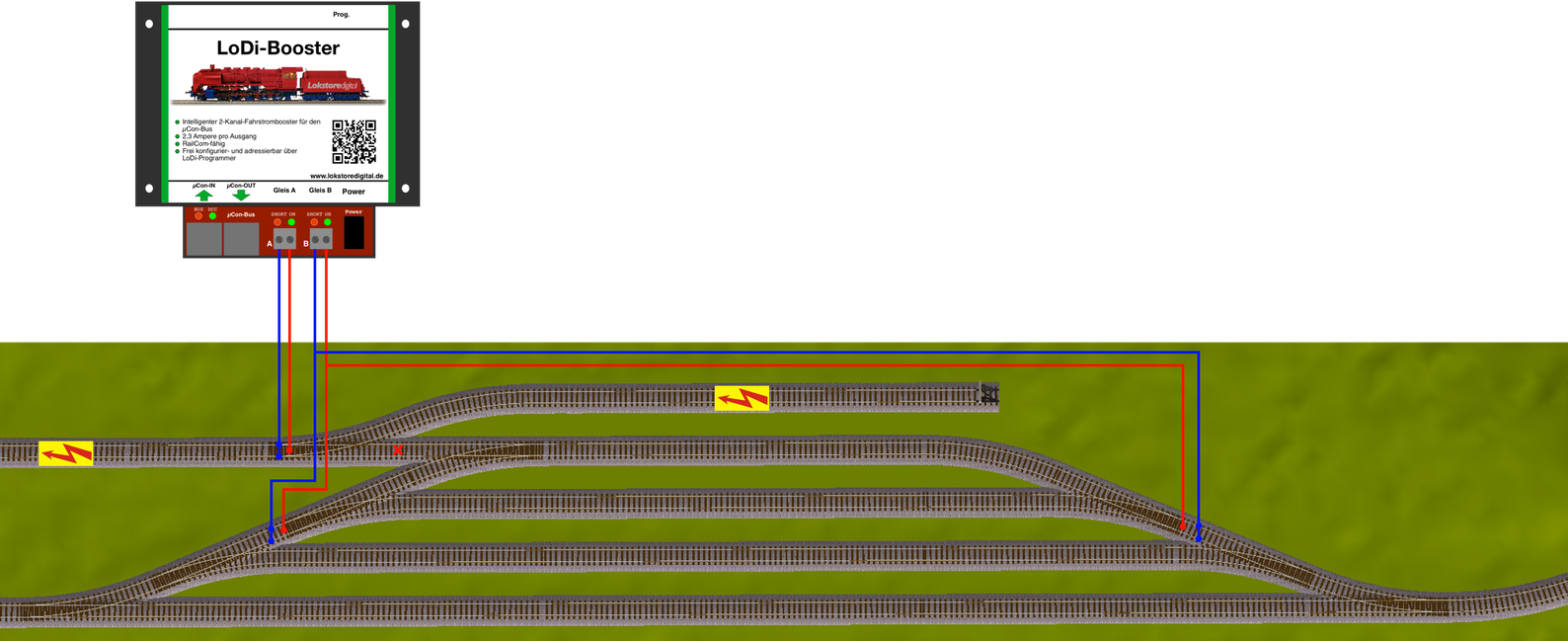
The LoDi-Booster has two separate outputs.
These let you divide your layout into logical sections. The built-in intelligent booster control can pass a short circuit through the LoDi-Rektor to the control software, so that only the section in which the short occurred is cut. All other sections can carry on unhindered.
If you have questions or are unsure about this, do turn to our forum or write us an email.
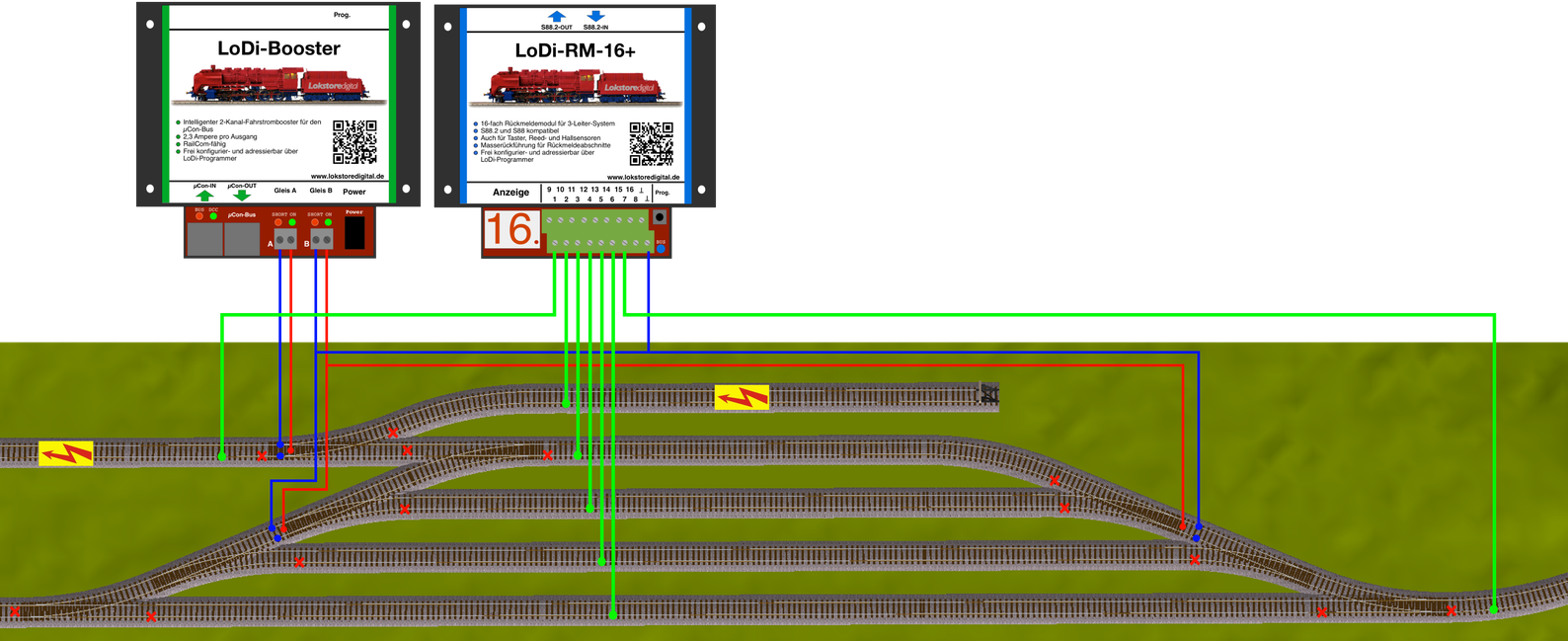
In the picture you see our new feedback module for three-rail track, the LoDi-RM-16+.
The module shown here produces the occupancy report from a measuring current of its own.
Beyond that it also supplies the reporting track with the common through what is known as the diode trick.
Please always watch for sufficient cable cross-section from the booster to your feedback module.
Other feedback systems can be integrated in a similar way.
No cable below 0.75 mm² should be used.
RailCom feedback can be evaluated per block on the three-rail system too.
Modern control systems support this loco-specific reporting per block.
Imagine the centre rail simply becoming the common. Since the common on the layout may always be one, you do not have to separate the new common either.
Which means the centre rail is always joined throughout.
If you have already separated the centre rail on an existing layout, it can be joined again, or you can run the booster sections with the common separated.
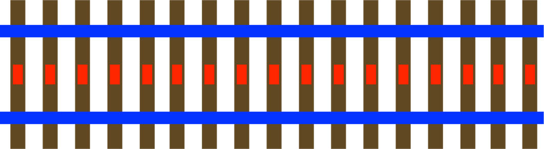
Here you see the normal standard method used with three-rail.
So the centre rail, RED, is B; the common rails above and below, BLUE, are O
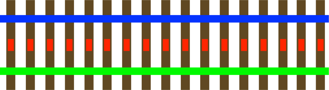
In this example you see the upper side carrying the common, BLUE, that is O.
The centre rail stays RED, that is B.
The lower side of the track is now the detector for the common report, that is GREEN, as has been usual for reporting with the three-rail method.
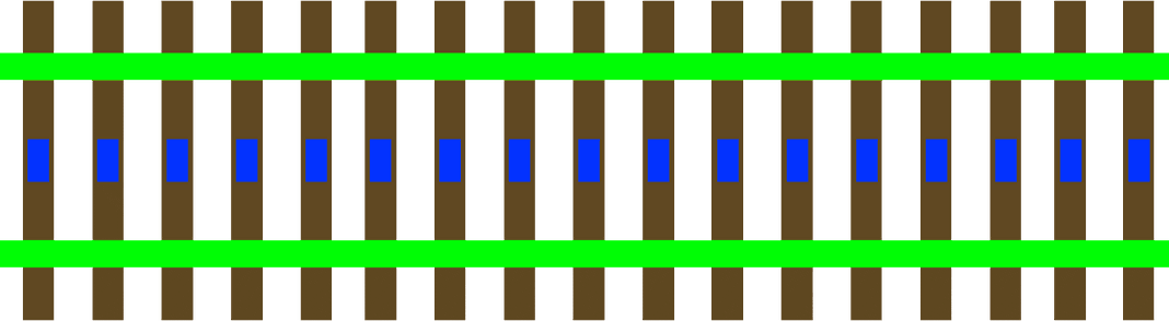
So that the locomotive's RailCom data also reaches the control software per block, we have to route the current through a feedback module of the kind used on the two-rail system, applied here to the three-rail method.
It takes a little rethinking, but we know from numerous customers that this solution works perfectly.
It would of course also be possible to report through the centre rail; many of our customers do this very successfully on three-rail layouts still fitted with metal track.
One thing has to be borne in mind, though:
The locomotive entering the track, or a detection section, only reports once the pickup shoe arrives. Because the shoe sits in a different place on every locomotive, braking distances can shift from one locomotive to another.
With the method described above, by contrast, the report is triggered by the first current-carrying wheel.
This example shows the block division for three-rail systems with RailCom feedback.
Note that every block and every route, or indeed individual turnouts, now needs its own detector connection.
If you use more than one detector per block, the wiring scheme naturally changes.
More detail on setting up the detectors can be found under the feedback modules in the feedback system and with our RailCom capable feedback module, the LoDi-8-GBM.
8. Connecting to two-rail track
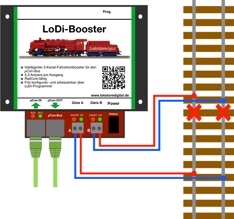
With two-rail running the common lines are usually not joined to one another. There are variants built with a joined common, however. That makes no difference to the LoDi-Booster; the commons of all boosters may be joined.
As with three-rail, on the two-rail system you have to watch for sufficient cable cross-section, whatever the scale. Do not use cable below a cross-section of 0.75 mm².
A short circuit can only be detected if enough current flows. Suitably thick cable ensures that.
The maximum cross-section for the screw terminals on the booster is 1.5 mm².
Many customers have asked us in the past how they should divide up the booster circuits, how many circuits are needed and where the divisions are best placed.
With this example we show you how best to divide and feed.
A simple test tells you whether there are enough circuits, and therefore feed points.
Create a short circuit on the track while it is powered. If it is no longer registered as a short, you should add another feed point and thereby another booster circuit. Without a further feed, in the event of a short the booster could put full power on the track and, together with the resistance of the track, no longer drive the voltage above the value at which the booster would detect a short.
The LoDi-Booster has monitoring built in, which additionally detects a short circuit in a flash.
The be-all and end-all of a smoothly running layout is the wiring.
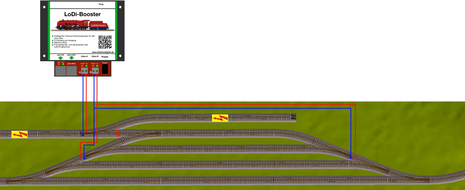
The LoDi-Booster has two separate outputs.
These let you divide your layout into logical sections. The built-in intelligent booster control can pass a short circuit through the LoDi-Rektor to the control software, so that only the section in which the short occurred is cut.
All other sections can carry on unhindered.
The common does not have to be separated on the track and can be joined between the LoDi-Boosters through the track itself.
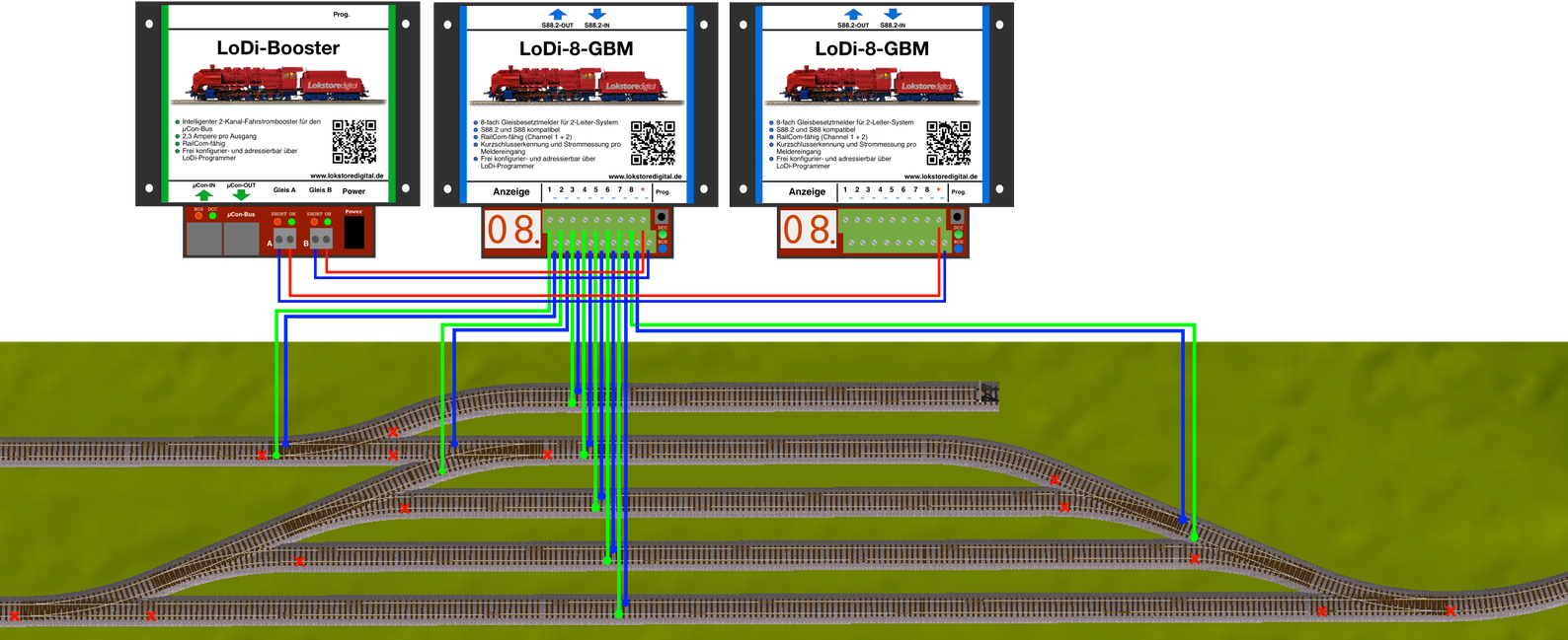
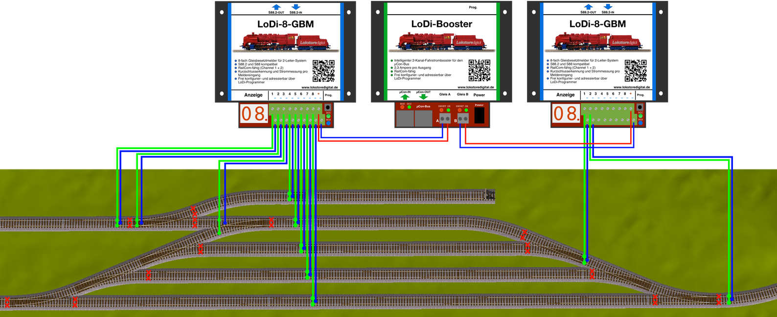
This example shows how you can supply a layout with the LoDi-Booster while feeding the current through the feedback modules. That is necessary on the two-rail system so that monitoring can take place.
Out of the many two-rail detectors on the market, we decided to show you our own system.
The module shown here receives its voltage from the LoDi-Booster; outputs 1–8 on the LoDi-8-GBM now supply the individual blocks with booster current. As you can see, we have drawn the commons of the blocks in a lighter shade.
Booster channel B feeds another occupancy detector supplying a further part of the layout.
Please always watch for sufficient cable cross-section from the booster to your feedback module.
You should not use cable below 0.75 mm².
We accept no liability for incorrectly laid-out blocks, as these have to be created specifically for the control software.
If you are unsure, friendly modellers in our forum will gladly help you.
9. Dividing the layout into booster sections
With the intelligent booster system we bring logic to the track, so that a short circuit does not bring the whole layout to a stand. The data is passed to the control software, which then knows where the short happened and holds trains before they enter other booster areas that are shorted or switched off. For that you naturally have to divide up your layout, or rather the track plan. Two booster outputs are available per device. That means you can secure very good logic and operating sequences with only a few units. Here is a small example of a division.
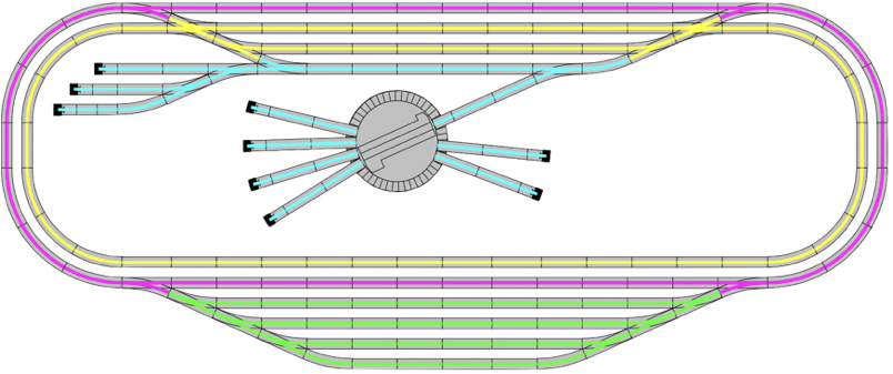
In this example we use two LoDi-Boosters, which gives us four power sections. The different circuits are colour-coded. If a short is now detected in one of these areas, that is passed to the LoDi-Rektor, which forwards the affected track section to the control software. The rest of the layout keeps running where possible.
10. Bridging the LoDi-Booster outputs
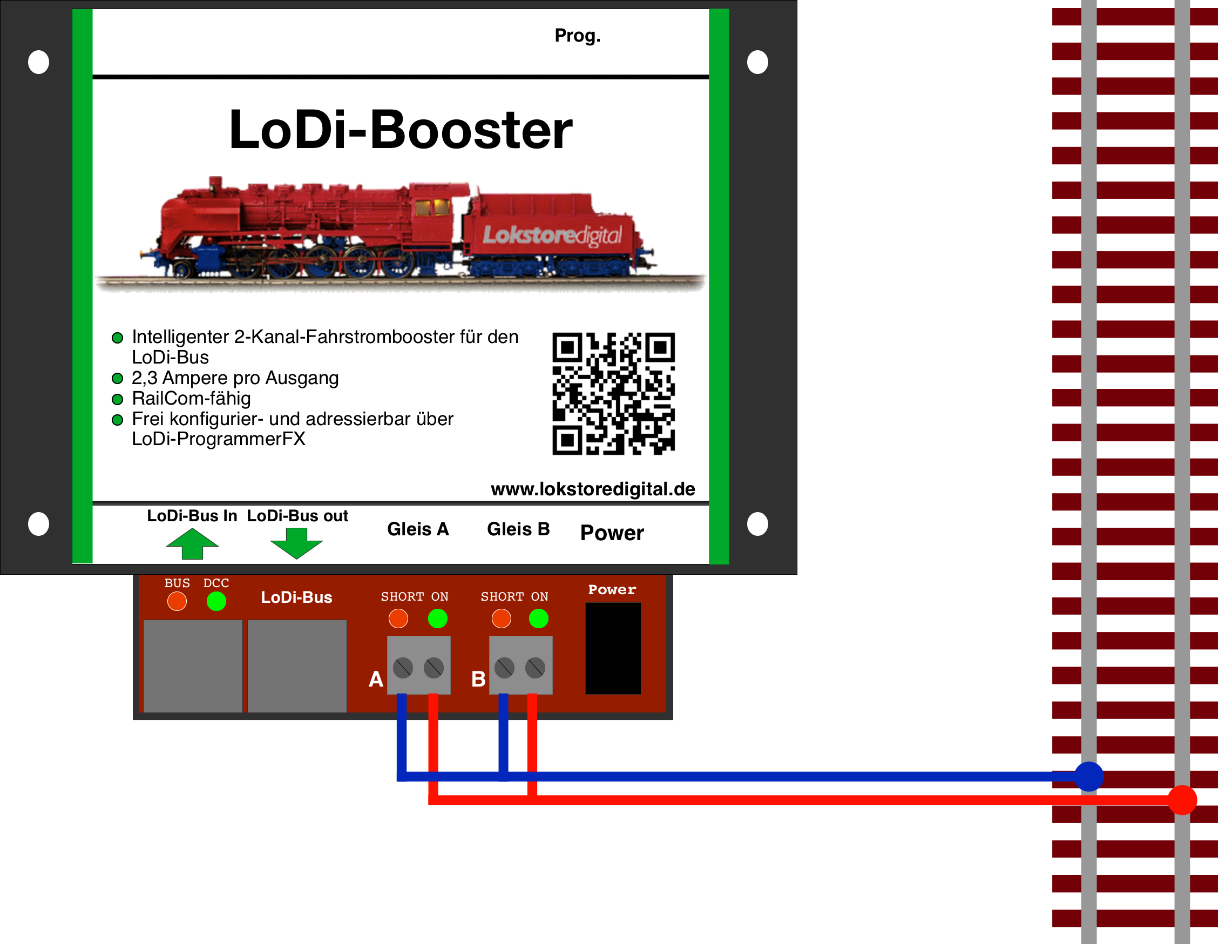
If you run a larger staging yard on your layout, or work in a larger scale and need more than 2.3 amperes, you can bridge the two booster outputs.
That is no problem with the LoDi-Booster.
Connect the outputs for track A and track B in parallel, that is bridged, to the track, as the diagram shows. That makes a maximum of 5 amperes available.
Please watch for a sufficient cable cross-section when doing so!
Under the Service heading you will find our recommendations for cable sizes and colours.
11. Technical data
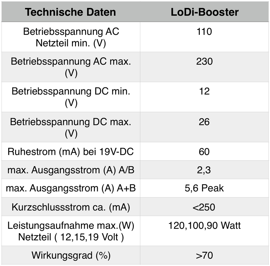
The LoDi-Booster has a total output of 5 A across two outputs of 2.3 A each.
2 × 2.3 A plus peak = 5 A
The two outputs are logically separated from one another.
It has thermal overload protection, which makes sure the LoDi-Booster takes no damage when overloaded.
Dimensions:
Length: 130 mm
Width: 115 mm
Height: 45 mm
Weight: 275 g
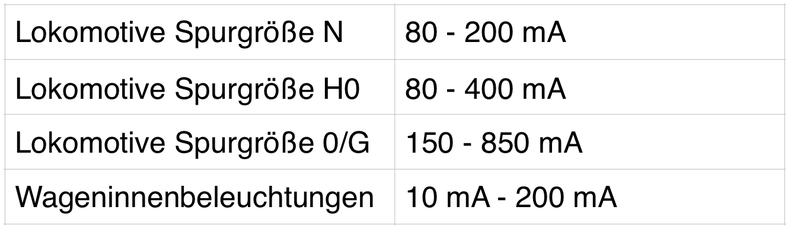
This table gives you a rough estimate of the current draw.
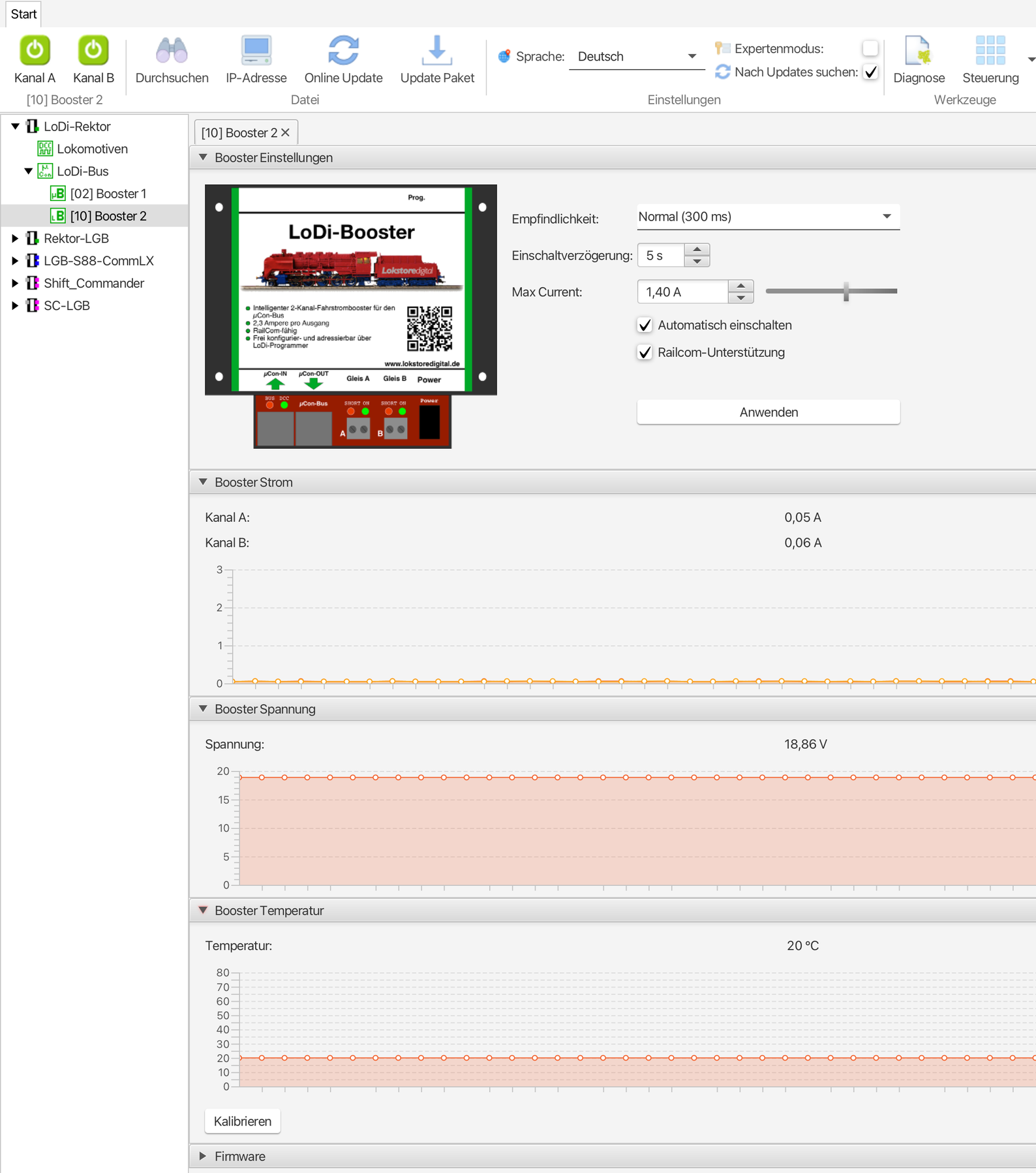
12. Setting up the LoDi-Booster in the LoDi-ProgrammerFX
and updating the firmware Here is how to set up the LoDi-Booster
13. LoDi-Booster PDF download
Here you can download a summary of the LoDi-Booster hardware and software as a PDF.