
Hardware
LoDi-CV-Programmer
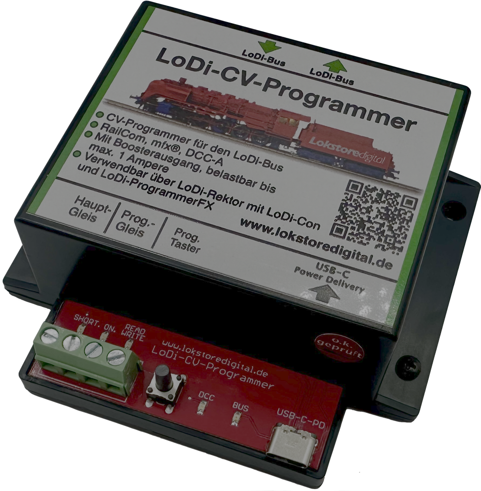
The time has finally come! 🎉 The LoDi-CV-Programmer is here!
It is the newest member of the LoDi bus family and plugs comfortably into the LoDi-Rektor or behind other LoDi bus devices. To keep it current we gave it modern USB-C PD technology — so the device's voltage can now be tailored to the job.
And that is not all: besides being a programmer it can also serve as a small booster of up to 1 ampere. Best of all? Alongside the common DCC protocol it can also talk to mfx decoders — and of course we have thought ahead: DCC-A is in preparation! 🚀
In short: a real all-rounder for your layout! 🔧✨
Features of the LoDi-CV-Programmer
- A professional programmer for the DCC and mfx® data formats.
- Prepared for the coming DCC-A data format.
- A fully integrated LoDi bus component from LoDi-Rektor version 03.04.05 onwards.
- Automatic registration of every mfx® capable locomotive.
- Full RailCom support — comfortable reading and writing of CVs on the main track.
- Convenient configuration of the LoDi DCC accessory decoders as well as decoders from other manufacturers.
- Modern power over USB-C PD (Power Delivery) with an output voltage adjustable from 9 to 20 V through the LoDi-Con or LoDi-ProgrammerFX.
- A built-in mini booster of up to 1 ampere output — ideal for smaller layouts.
1. The LoDi-CV-Programmer and its connections
The LoDi-CV-Programmer is a versatile programmer that works seamlessly with the LoDi bus (formerly µCon bus). The LoDi-Rektor is needed as the central control unit.
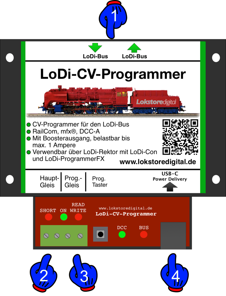
The LoDi-CV-Programmer has the following connections:
- (1) LoDi bus input: the LoDi bus is fed into this socket. LoDi bus OUT: further LoDi bus devices connect here
- (2,3) Track output and programming track output: the track output can carry up to 800 mA continuously and 1.1 A peak. The programming track output is limited to a maximum of 500 mA during normal programming.
- (4) Connection for the supplied power supply: the LoDi-CV-Programmer has a USB-C PD connector. That means it has to run from a USB power supply that supports Power Delivery (PD). You will find more on that below in section 3 — connecting a power supply.
2. LEDs and programming button of the LoDi-CV-Programmer
The LED indicators on the LoDi-CV-Programmer give you information that helps with troubleshooting and with setting the device up.
- (1) "Short" = this LED indicates a short circuit at the booster output. As soon as a short is detected, the LED starts to flash. "On" = as soon as this LED is lit at the respective output, the output stage of the LoDi-CV-Programmer is active, meaning power is present at that output.
- (2) "DCC" LED = this LED is lit continuously as soon as the booster receives a signal over the bus — DCC, Motorola or M3 alike. If no bus cable is plugged in, or the LoDi-Rektor is switched off, the DCC LED flashes rapidly. "BUS" LED = shows the state of the LoDi bus. When the bus signal is detected, the LED lights with a short pulsing interruption.
- (3) Programming button: every LoDi bus device has its own address through which it is addressed on the bus. To set a new address the button has to be pressed first. The address is then assigned through the commissioning software LoDi-ProgrammerFX or the LoDi-Con.
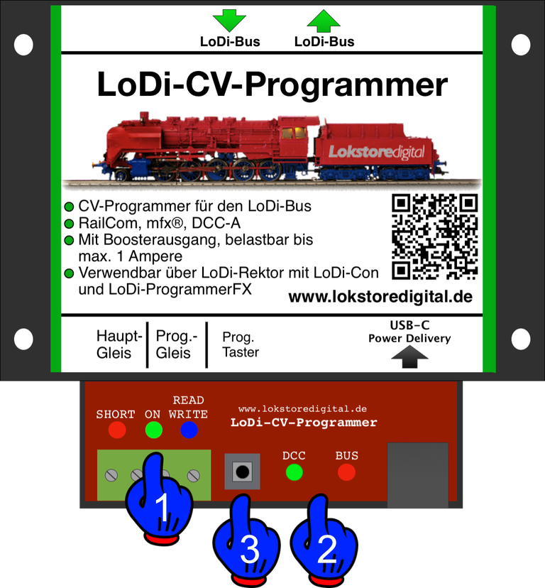
A short tap of the button switches the track output off and on again. The "ON" LED goes out or lights up accordingly.
The prog. button is also used to programme the address. The LoDi bus provides 63 addresses. Held for more than 3 seconds, the bus and DCC LEDs flash red and green alternately. This can be interrupted by pressing the button again, or it ends when a new address is sent to the LoDi bus device over the bus. Once the device understands the signal, programming ends and it returns to normal operation.
3. Connecting a power supply
USB-C Power Delivery (PD) — flexible and safe power. The LoDi-CV-Programmer is delivered with a 45 watt USB-C PD power supply providing the following voltages:
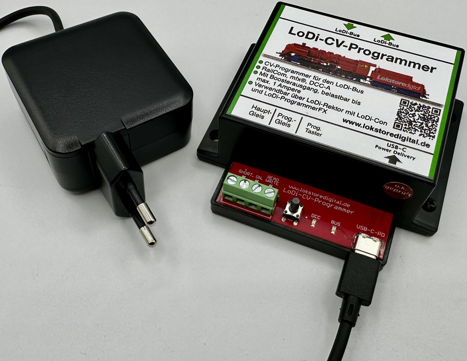
20 volts → for gauge 1, G, 0, H0 (Märklin)
15 volts → for H0, H0m, H0e, TT, N
12 volts → for scales smaller than N
9 volts → for Z and smaller
The supplied power supply has been tested specifically for the LoDi-CV-Programmer and guarantees a stable, safe supply.
⚠️ Please do not use power supplies of unclear origin, to avoid possible malfunction or damage.
Voltage individually adjustable
The output voltage you want can be set comfortably through the LoDi-ProgrammerFX or the LoDi-Con. That way the LoDi-CV-Programmer can be matched perfectly to the scale you are working in.
What is USB-C Power Delivery (PD)?
USB-C Power Delivery (PD) is an intelligent fast-charging and power protocol that can supply different devices at different voltages and power levels. Unlike conventional USB power supplies, which often deliver only one fixed voltage (5 V, say), a USB-C PD supply can negotiate the voltage needed dynamically — in our case, for different model railway scales.
Advantages of USB-C PD for the LoDi-CV-Programmer
✔ Voltage freely adjustable: the voltage you need is easily set through the LoDi-ProgrammerFX or the LoDi-Con.
✔ More power and efficiency: with 45 watts there is always enough headroom for operation.
✔ Future-proof and universal: USB-C PD is an open standard that is spreading steadily — many new power supplies already carry it.
✔ Protection against overload and wrong voltages: the PD standard protects connected devices against excessive voltage or the wrong supply.
Why not a conventional power supply?
Unlike classic model railway supplies with one fixed output voltage, USB-C PD offers the flexibility to provide different voltages — ideal for universal use across different scales. Or indeed to protect the electronics in a locomotive after a digital conversion.
4. Connecting to the LoDi bus

The LoDi bus — reliable communication between components. The LoDi bus (formerly µCon bus) was originally developed to carry data over long distances stably and without loss. While it was intended specifically for boosters at first, it has since grown into a versatile communication system for the various LoDi components.
On the LoDi bus the devices are connected one behind another in a line; star wiring is not provided for.
From LoDi-Rektor firmware version 3.4.5 the LoDi-CV-Programmer is fully integrated into the bus and in continuous exchange with the LoDi-Rektor. The LoDi-Rektor supplies the LoDi-CV-Programmer with the control data it needs and sends it over the LoDi bus. But communication does not run in one direction only. The LoDi-CV-Programmer can also send data back to the LoDi-Rektor, which then feeds into the LoDi-ProgrammerFX, the LoDi-Con or the control software. That includes readings such as current and voltage measurements, short-circuit status monitoring, power supply monitoring and the current device temperature, among much else.
Through the LoDi-Rektor combined with the LoDi-ProgrammerFX and the LoDi-Con, numerous settings can be made for the LoDi-CV-Programmer. The short-circuit sensitivity can be adjusted, for instance, or the address managed.
6. Connecting to the track
With the small booster built into the LoDi-CV-Programmer, small layouts with up to five locomotives can be run without trouble — depending, of course, on how much current the individual locomotives draw. In our tests with a compact layout and five trains, the LoDi-CV-Programmer handled operation reliably.
Do bear in mind, though, that the LoDi-CV-Programmer was designed primarily as a programmer. The built-in booster is ideal for small test set-ups and running at low power. Endurance testing shows that a load of up to 0.8 A is optimal, while up to 1.1 A remains possible briefly.
If a larger layout or a higher current draw is wanted, a LoDi-Booster is the way to go. It provides a stable, capable supply and allows safe, reliable operation with several trains and additional lighting or digital consumers.
CAREFUL!
The LoDi-CV-Programmer needs a separate supply and is electrically isolated from the LoDi-Booster or LoDi-Booster 10A. It is therefore not possible to drive from a booster-fed section straight across an insulated joint into the programming area. To avoid damage we recommend moving the vehicle into the programming area by hand or over an isolating track section.
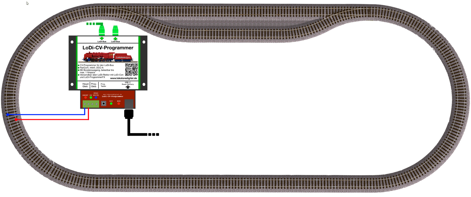
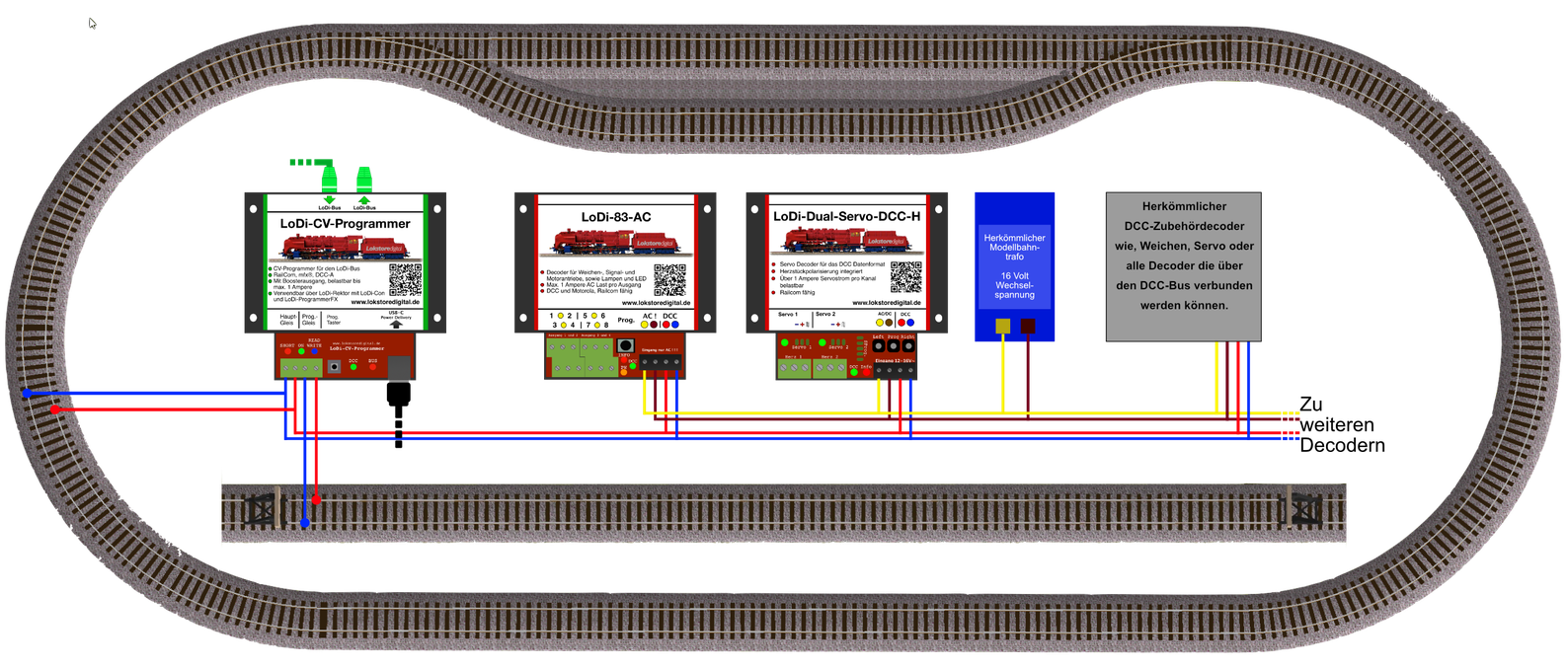
If you have built a small test circuit and want to run it from the LoDi-CV-Programmer, you can use the main track output directly for that.
Please note that either the main track or the programming track can be active — never both at once!
At the programming track output the LoDi-CV-Programmer provides a maximum of 500 mA.
7. Connecting the programming track
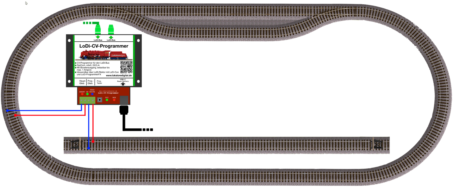
As mentioned above, the LoDi-CV-Programmer has two outputs: the "main track output" (left) and the "programming track output".
At the programming track output you have up to 500 mA available for programming. The programming track should be a separate section of track on which you can programme one vehicle or decoder at a time, free of interference.
In our diagram we have set up a separate piece of track as a programming track in addition to our small running circuit.
One more important note on programming a locomotive on the programming track: why should there be only one locomotive on it?
The programming track is designed specifically to detect individual locomotives and to read or change their CV values (configuration data). For that to work reliably, the command station has to know unambiguously which locomotive it is talking to.
If several locomotives stand on the programming track at once, the following problems can arise:
- Wrong responses: the command station receives contradictory signals and cannot identify the locomotive correctly.
- Faulty CV programming: changes might be written to the wrong locomotive — or not at all.
- Short circuit: if the total of 500 mA is exceeded by several vehicles on the programming track, nothing can be read or written.
So the rule is: 👉 only ever put one locomotive on the programming track — then everything runs reliably and safely.
8. Connecting accessory decoders
Many customers use accessory decoders on their layouts, such as the LoDi-83-AC or turnout and signal decoders from other manufacturers.
With the LoDi-CV-Programmer you can supply these decoders with digital information directly from the main track connection. That removes the need for a separate booster output for the accessories.
DCC accessory decoders with RailCom support communicate bidirectionally through the LoDi-CV-Programmer. You can therefore read and programme the CVs of every connected RailCom capable accessory decoder live on the track. Beyond that, RailCom gives you immediate confirmation as soon as the decoder has carried out a switching command.
All LoDi DCC accessory decoders have RailCom and can therefore be configured fully through the LoDi-CV-Programmer.
Up to 30 turnout decoders can be run from one LoDi-CV-Programmer. The number actually possible depends on the current draw of the connected decoders. The built-in current display of the LoDi-CV-Programmer keeps you informed of the present demand at all times.
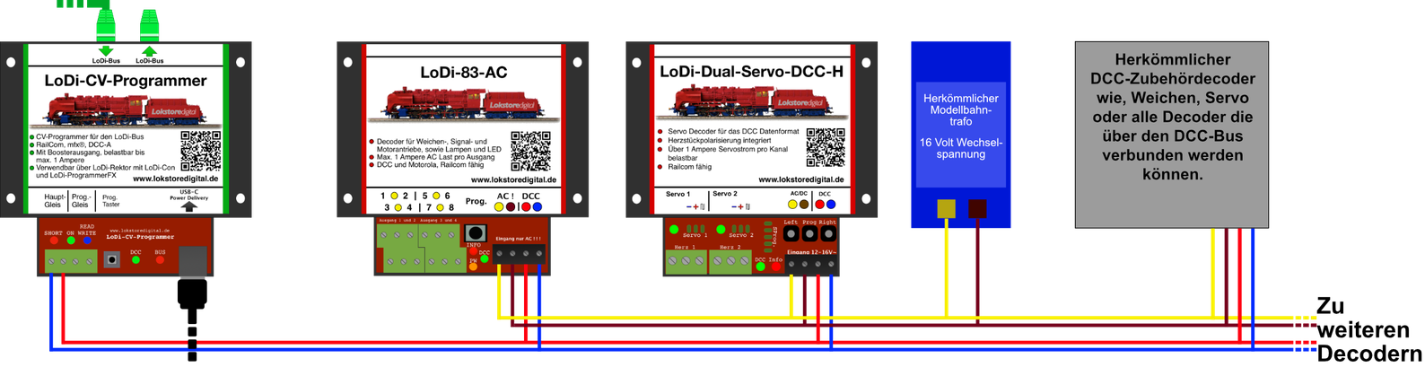
The programming track naturally remains available while the main track output is used for decoders or a short running section, for instance.
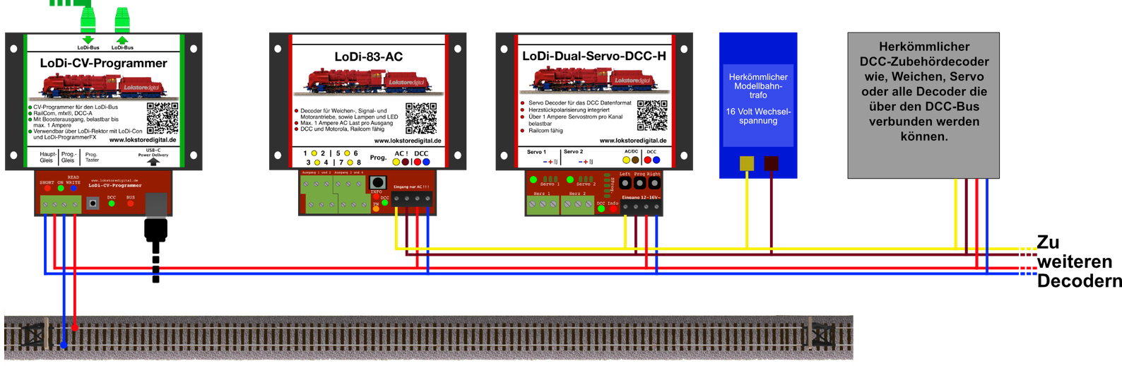
The next picture shows a small complete set-up. Further components can of course be added as needed, feedback modules such as the LoDi-8-GBM, for example.
9. Technical data
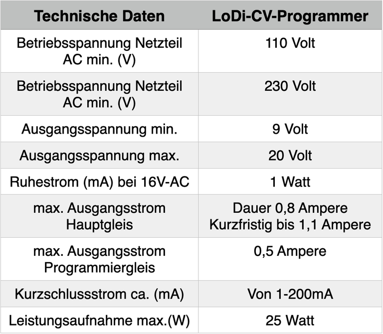
The LoDi-CV-Programmer has a total output of 1 A, of which 0.8 amperes are available continuously and up to 1.1 amperes briefly.
It has thermal overload protection, which makes sure the LoDi-CV-Programmer takes no damage when overloaded.
| Property | Value |
|---|---|
| Dimensions | Length: 89 mm |
| Width | 100 mm |
| Height | 35 mm |
| Weight | 90 g |
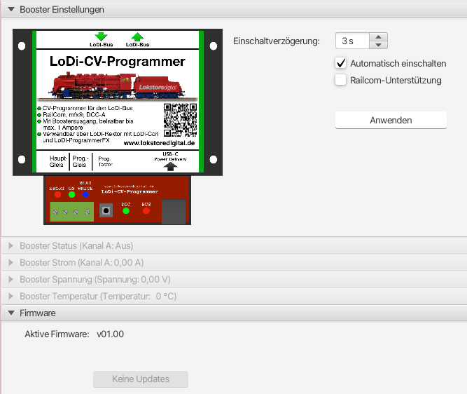
10. Setting up the LoDi-CV-Programmer in the LoDi-ProgrammerFX
and updating the firmware Here is how to set up the LoDi-CV-Programmer
11. LoDi-CV-Programmer PDF download
Here you can download a summary of the LoDi-Booster hardware and software as a PDF.