
Hardware
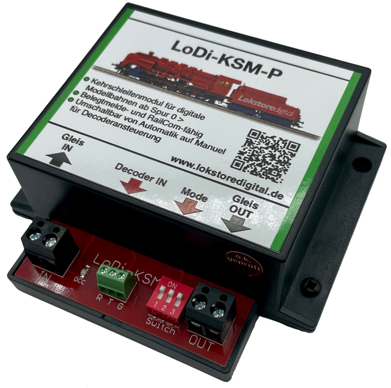
LoDi-KSM
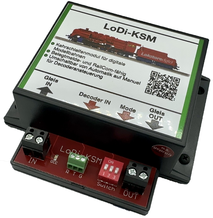
Why does a layout need a reverse loop module?
Reverse loop modules are generally only needed on two-rail systems.
The reverse loop module switches a reverse loop over automatically.
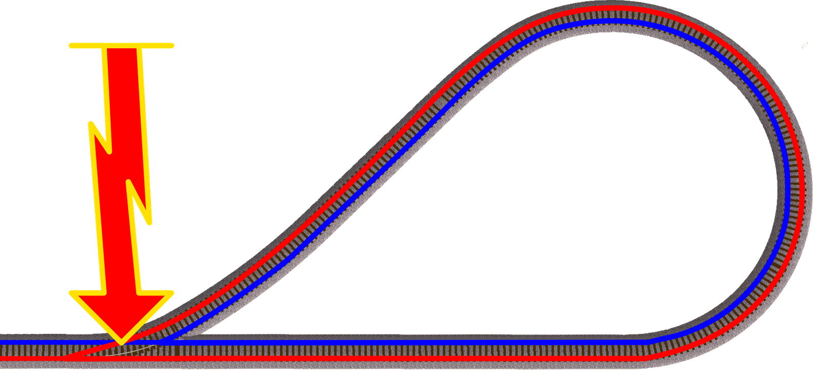
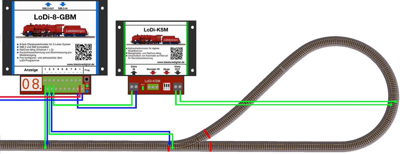
As the picture shows, a reverse loop occurs when a train reverses or turns within a loop of track and the power feed crosses over as it rejoins the track.
Here you can see the red line crossing the power over the blue line.
That is what is called a reverse loop.
To avoid the short circuit that would result, you need a special switch or relay that reverses the polarity of the track supply inside the loop.
Scroll down to see how the device is used.
Features of the LoDi-KSM(-P)
- A reverse loop module (KSM) for your digital layout, for scales from Z to G.
- The reverse loop module is independent of the track format.
- Our KSM is invisible to feedback modules, which means your detector does not report "occupied" just because the reverse loop module is connected to it.
- Only the locomotive triggers an occupancy report, as usual.
- The KSM is fully RailCom capable. The locomotive's RailCom data on channels 1 and 2 is returned through the KSM section itself.
- You can switch between automatic and manual mode; for that you need an ordinary turnout output on your decoder or LoDi-Operator.
- Our modules support the LoDi-KSM(-P) with
- LoDi-Operator 16-SD-FL
- LoDi-Operator 4-WD-DC
- LoDi-Operator 4-WD-AC
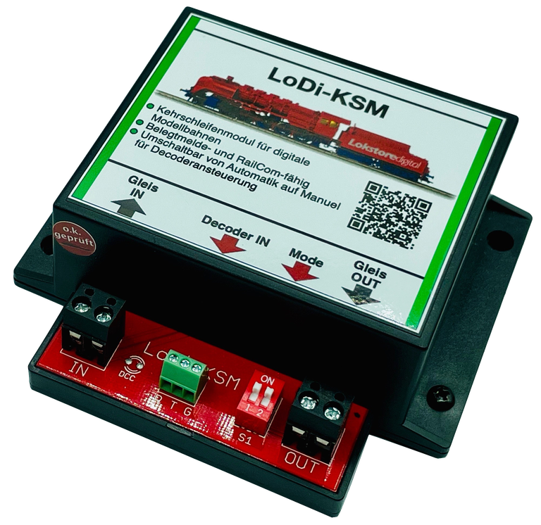
1. The LoDi-KSM(-P) and its connections
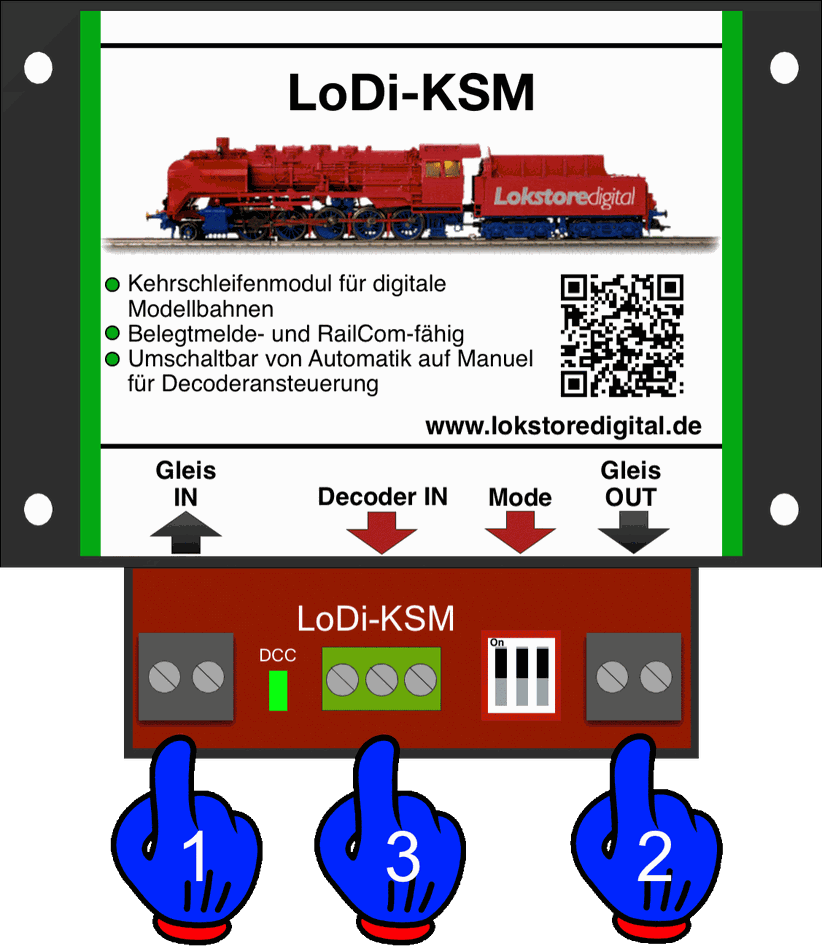
- (1): the track cable coming from the booster or command station connects here.
- (2): the reverse loop — the section of track inside the loop — connects here.
- (3): for manual operation through an accessory decoder.
2. Wiring in detail
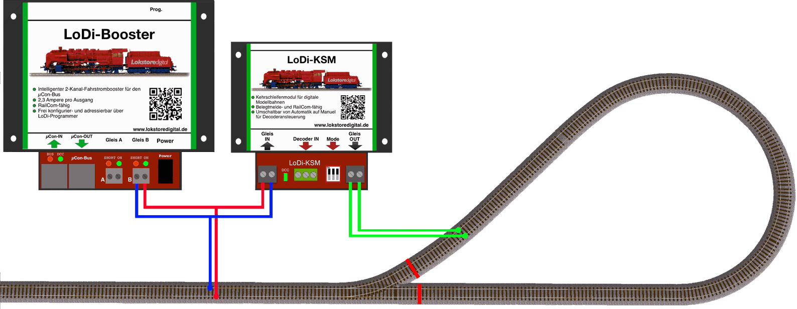
Here you can see how it is wired to a LoDi-Booster.
Any common command station and any manufacturer's booster can be connected to the LoDi-KSM(-P). The module works entirely on its own.
This example runs the LoDi-KSM(-P) through an occupancy detector.
That is what you need if you want your reverse loops reported back as occupied.
Occupancy detectors from any manufacturer can be connected to the LoDi-KSM(-P).
3. Connecting a LoDi-Operator or turnout decoder
As mentioned already, the
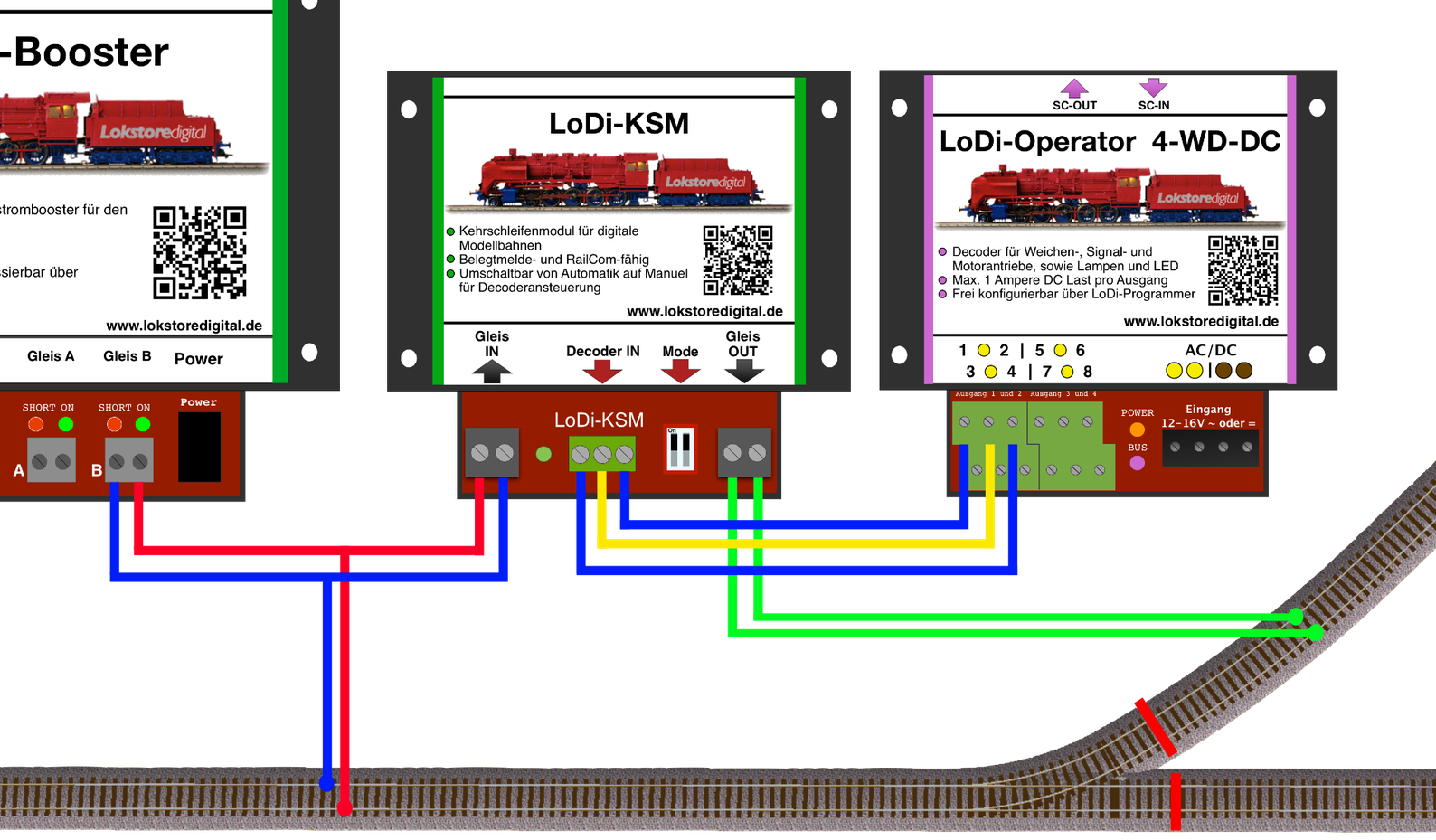
LoDi-KSM(-P) has a connection for a turnout decoder of any kind.
The next photo shows an example wired to a LoDi-Operator 4-WD-DC.
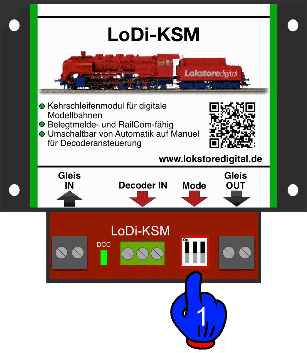
If you want to switch the module's automation off, both DIP switches at (1) have to be set to "off". The module can then only be driven through the turnout terminals (Decoder IN).
The module has two operating modes that can be set:
- DIP switches ON / ON — the module runs in automatic mode, that is, it switches over as soon as it detects a load. Manual operation is available in automatic mode as well, which gives a second safeguard.
- DIP switches OFF / OFF — the LoDi-KSM works only through the Decoder IN terminal.
LoDi-KSM(-P) modules from 6/2021 have a three-way DIP switch. DIP 1 turns the LED on and off; DIP 2 and 3 behave as described above.
4. Technical data
| Property | Value |
|---|---|
| Dimensions | Length 8.9 cm |
| Width | 10 cm |
| Height | 3.5 cm |
| Weight | 83 grams |
At the digital terminal, that is in digital operation, the decoder can be supplied with up to 26 volts.
Do mind the specifications of your command station or booster manufacturer here.
LoDi-KSM loadable by consumers with 3 amperes briefly and 2 amperes continuously
LoDi-KSM(-P) loadable by consumers with 6 amperes briefly and 4 amperes continuously
5. LoDi-KSM PDF download
Here you can download a summary of the LoDi-KSM as a PDF.