
Hardware
LoDi-Rektor
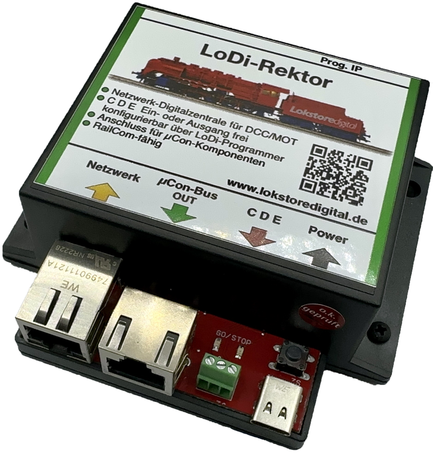
The director of the locomotives. It provides the all-important signal for the locos.
The LoDi-Rektor is a labour of love for us — a command station that handles every task and is broadly compatible.
It is a compact network command station, developed specifically for the needs of the computer-controlled model railway.
Features of the LoDi-Rektor
- It is the link between computer and locomotive. The raw loco data is generated by the computer and sent to the LoDi-Rektor, which then produces the track signal required.
- For sending, the LoDi-Rektor currently supports the following protocols: DCC, mfx® and Motorola. (To use M3 the loco's UID must be known; the Rektor cannot read it.)
- The LoDi-Rektor drives the connected components over the LoDi bus (formerly µCon bus). The LoDi bus was developed as a booster bus and has been developed further by us. It is fully backwards compatible with the old µCon devices, which can be connected to the µCon bus.
- The LoDi-Rektor can be used purely as a booster interface, with your own command station connected to C D E. The C D E is switched from OUT to IN comfortably through our LoDi-ProgrammerFX.
- The C D E-IN can be used as a sniffer for conventional DCC command stations. (From version 2023.08.)
- A modern network interface, and therefore driver-free operation.
- Command station and track signal generator in the latest version 2.0. Faster processing from PC to LoDi-Rektor, less data traffic, more efficient handling.
- Suitable for layouts of every size — small, large or larger still. The LoDi-Rektor has ample power to handle even the biggest layouts with ease. Should your layout nonetheless reach a size at which ordinary command stations meet their limits, simply add a second LoDi-Rektor to the system. So-called hand-over points can be configured comfortably for that.
Videos from partners
Walkthrough by Wolfgang Radermacher covering the LoDi-Rektor and LoDi-Booster.
A short demonstration of the LoDi-Rektor with the DC-Car system.
1. The LoDi-Rektor and its connections
The LoDi-Rektor is the interface needed to generate the required loco data formats.
At present the LoDi-Rektor supports DCC, M3 and Motorola in all their variations.
The only limit here is the control software. It connects through a modern, forward-looking and driver-free interface.
It is therefore entirely independent of the operating system installed.
You should, however, have the latest Java version installed.
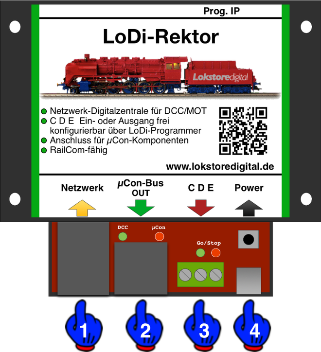
About the connections on the LoDi-Rektor:
- (1) Network port: connect your network switch or router here.
- (2) LoDi bus OUT: LoDi bus components such as the LoDi-Booster, or other LoDi bus components, connect here. You may also mix in components from other manufacturers — the LoDi-Rektor detects which device is attached.
- (3) CDE: conventional boosters supporting the CDE standard can be connected here. If you already have a command station and want to work with it, the CDE output can be reconfigured as an input or sniffer-in through the LoDi-ProgrammerFX.
- (4) USB-C port: the USB-C connection serves solely as the 5 volt supply for the LoDi-Rektor.
2. LEDs and buttons of the LoDi-Rektor
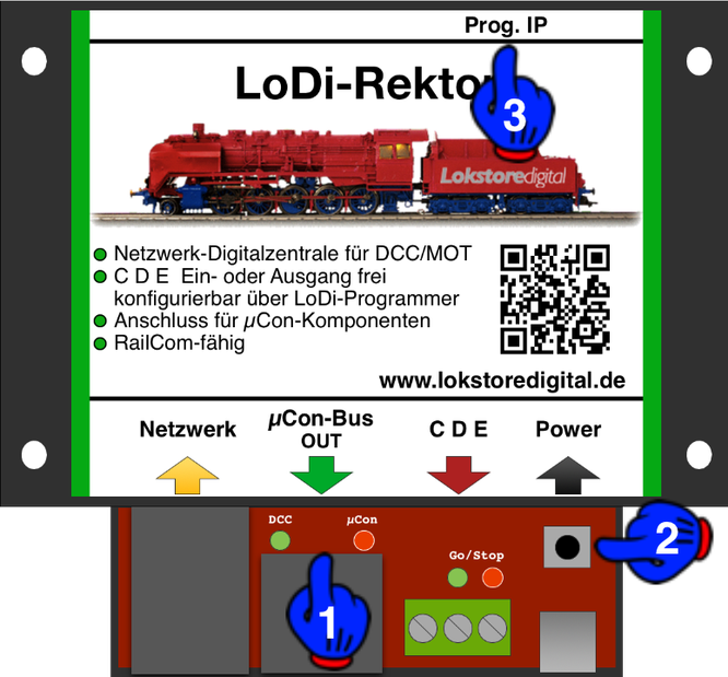
The LoDi-Rektor has several LEDs and buttons to help you read the state of the device and understand faults quickly.
- (1): this shows the activity of the µCon bus, and the green LED shows DCC. It lights as soon as the LoDi-Rektor sends a data signal. The red LoDi bus LED pulses at a steady rate, which tells you the bus is active.
- (2) Start-stop button: think of this as an emergency stop. Pressing it interrupts the track signal and all boosters stop immediately.
- (3) Prog. IP button and LED: this button is used whenever you want to change the IP address of your LoDi-Rektor. More on that in the LoDi-ProgrammerFX description.
3. Connecting the power supply to the LoDi-Rektor
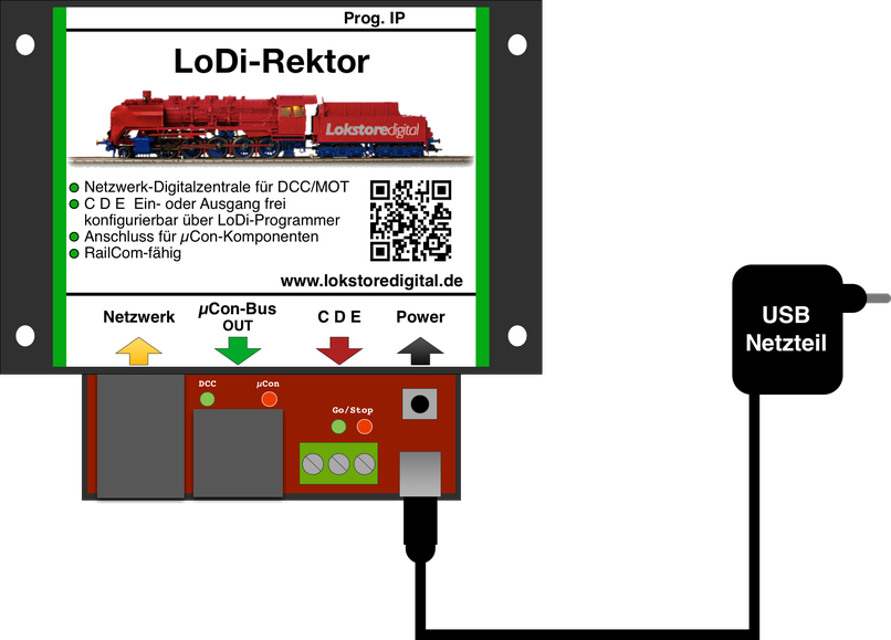
We deliver the LoDi-S88-Commander LX with a high-quality USB power supply. You are of course welcome to use your own USB power supply, but it should provide at least
1 ampere at 5 volts.
(Chargers from newer Apple MacBooks or iPads unfortunately cannot be used. They work with
"USB Power Delivery", where the devices have to negotiate the current — a function the LoDi components do not support.)
Important note on the power supply: use only the external power supply for our interface. Powering it from the PC can cause a ground loop and interference because of the network connection.
4. Connecting the LoDi-Rektor to the network
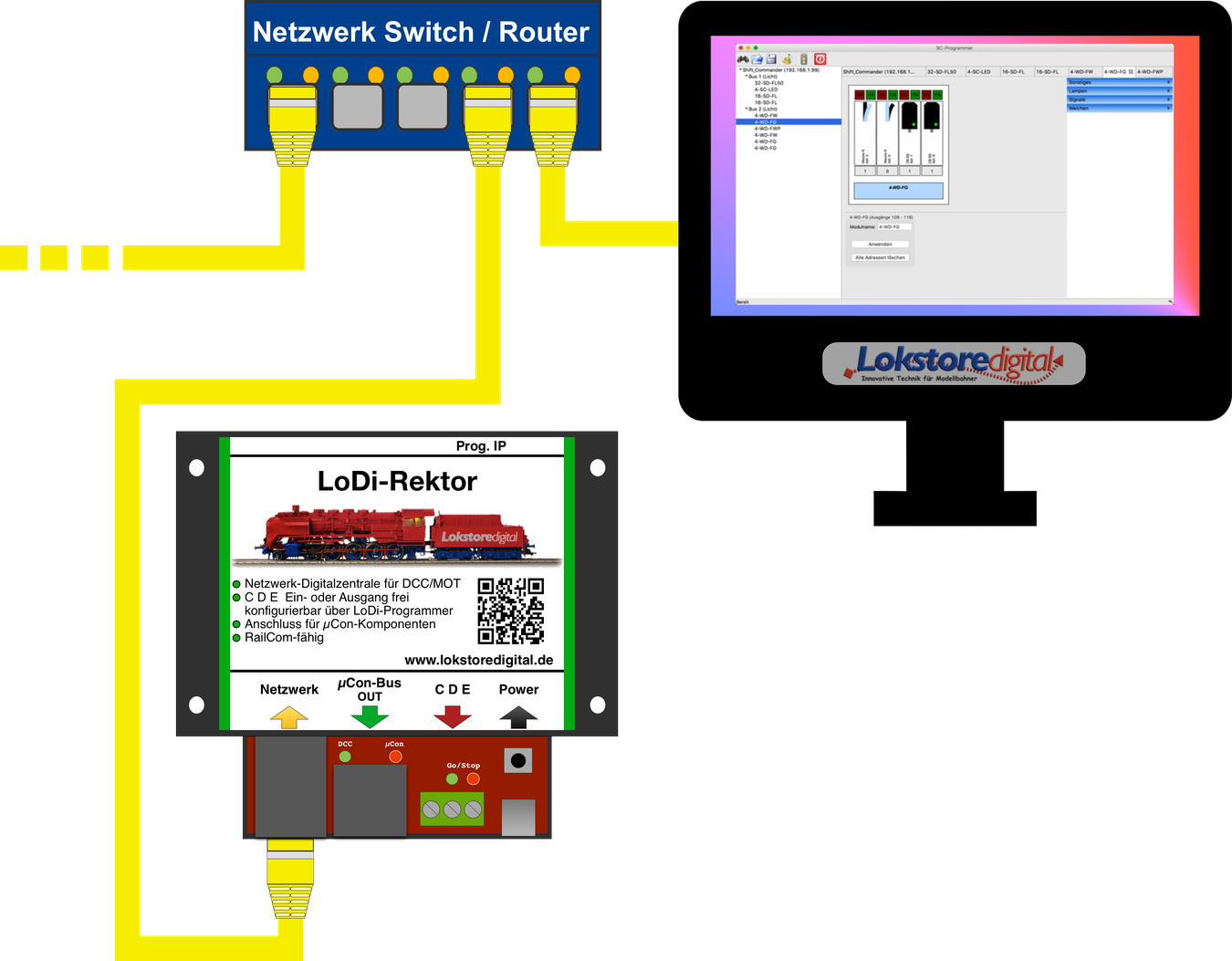
All our devices work with a modern network interface.
That brings you plenty of advantages in handling the devices. This network interface lets you integrate several interfaces into your system without trouble.
There are almost no limits to your imagination here.
This technology lets you build large and very large layouts, but small layouts benefit from it too.
Thanks to networking, controlling your layout from a laptop or tablet is no longer a problem. Today's Wi-Fi routers are perfectly able to carry these connections quickly enough.
There is little to watch out for when bringing the LoDi interface into your network.
It is always easier to integrate the LoDi interface into an existing network than to install another network card in the computer.
If you need help with the integration, do get in touch with us through the contact form, or turn to our users in the forum, who will gladly help.
As the picture above shows, we pay close attention to the colour coding of network cables. Yellow is the international standard for computer networks.
You are of course free to use other colours; we stick to these standards.
In the example shown, the computer is connected to a switch or router.
You can of course also connect the computer over Wi-Fi.
The LoDi-Shift-Commander is attached to the switch or router as well.
The cable running off to the left could be your internet line, or other devices connected to your network.
If the ports on the switch or router run out, simply connect another switch to the existing one. The link channels of the switches route the data to the right device automatically; you only have to plug the cables in. Please take care not to build a loop, though — a loop is a circle, so to speak, that will bring your network down.
Once the LoDi interface is connected correctly, the next step is configuring the network address (the IP address) through our LoDi-ProgrammerFX.
5. Connecting the LoDi-Rektor to the LoDi bus
The LoDi-Rektor carries the LoDi bus, formerly the µCon bus. It was originally developed as a pure booster bus for the µCon system of the day. As the LoDi bus it has been, and continues to be, developed and maintained.
The LoDi bus offers many advantages for boosters in particular, because it lets us run long network cable lengths — up to 1500 metres is possible.
Boosters receive the same signal everywhere; there is no timing offset in the track protocol.
For large installations in particular the LoDi bus is the perfect choice.
Beyond that, the LoDi bus brings us plenty of information such as:
- Current draw of the individual booster outputs
- Booster status
- Voltage reading
- Temperature monitoring
- Free addressing of the connected LoDi bus components
Here you see a LoDi-Booster connected to the LoDi-Rektor. The LoDi bus needs a terminating plug; one is supplied with every LoDi-Rektor.
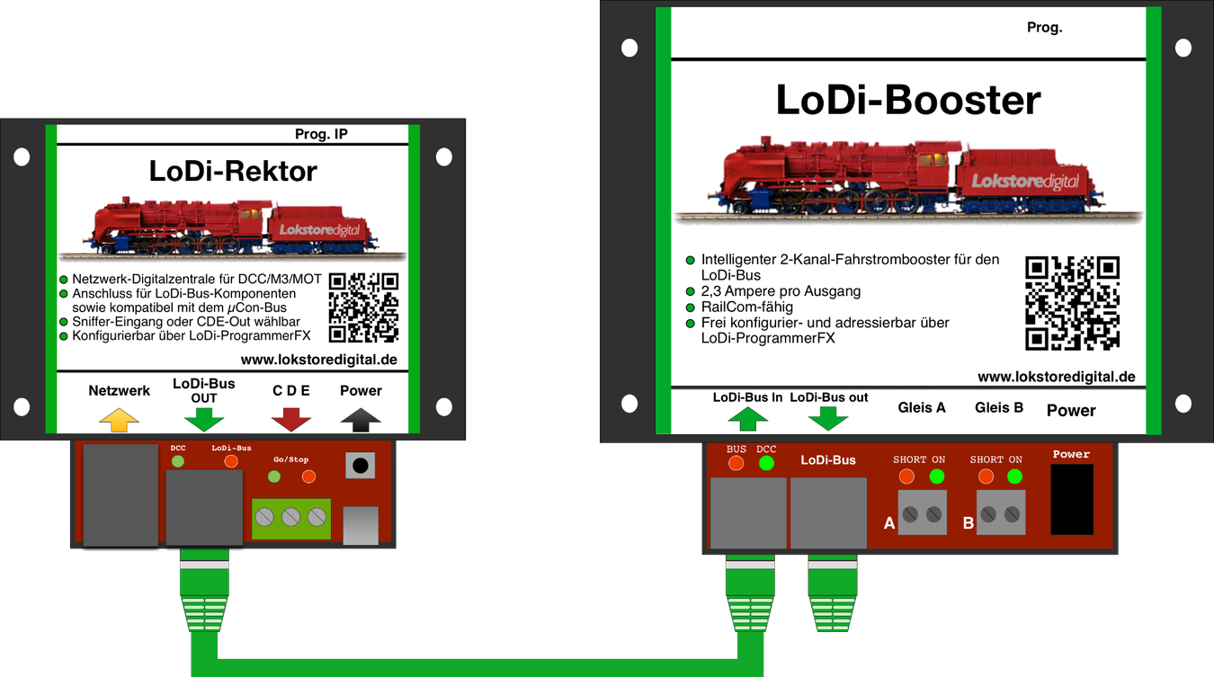
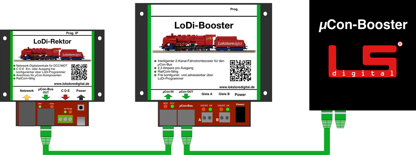
Our system is fully compatible with other LoDi bus components. The LoDi-Rektor automatically detects the connected component, whether that is a LoDi-Booster, a µCon booster or a Railspeed.
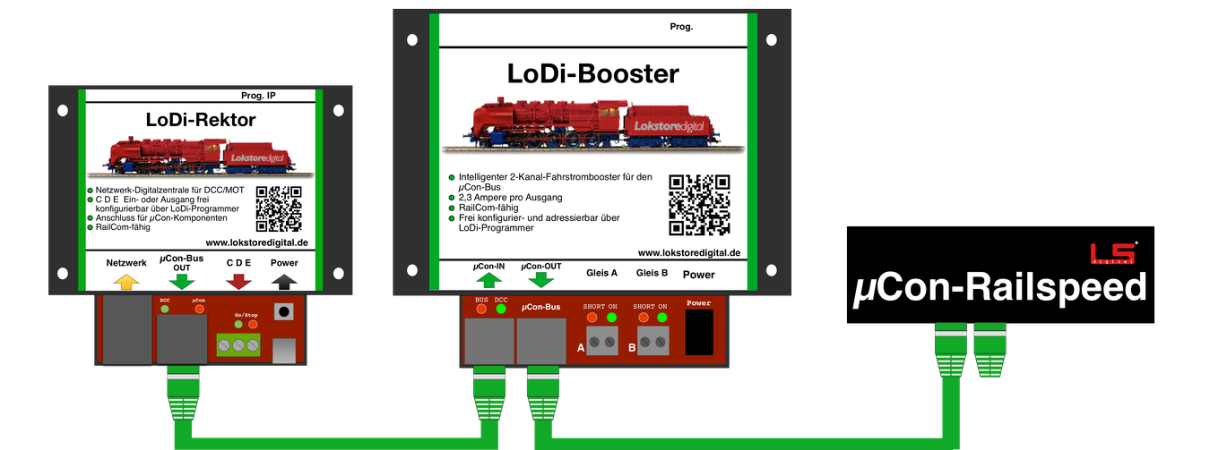
The Railspeed by LSdigital works fully on the LoDi-Rektor. It makes no difference where on the bus it is inserted.
6. Conventional boosters on the LoDi-Rektor
If you have boosters, are happy with them, and want to attach the LoDi-Rektor only as a command station or generator, you are of course free to do so.
Customers have also asked us repeatedly what they should do with their old boosters.
We say: connect them too!
Perhaps you still have a stretch of track that is not part of the layout, or you want to switch turnouts and signals over DCC, M3 or Motorola. All of that is possible.
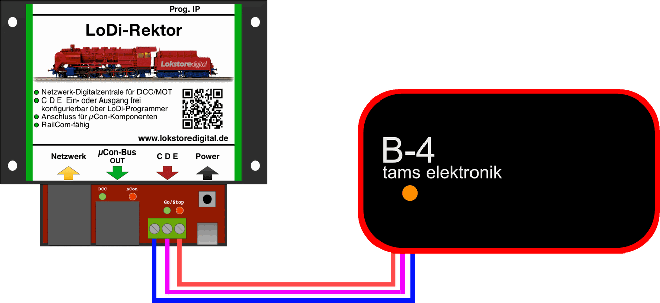
If the connected booster reports a short circuit on E, that is shown in our tool.
7. The LoDi-Rektor as a booster interface over C D E or sniffer-in
The LoDi-Rektor can be used as a command station with sniffer-in, or as a booster interface.
What does booster interface mean?
Many control programs support recognising where a short circuit is. There are ways to give the control software a pulse through feedback modules, saying that a particular booster circuit has a short.
The LoDi-Rektor, by contrast, collects the boosters' data itself and then sends it to the control software.
That lets you evaluate more data:
- Individual boosters are shown with their address
- Current draw and voltage can be displayed
- Booster temperature
- Booster status on/off, short circuit
The LoDi-Rektor has a switchable C D E input or output. You decide through the LoDi-ProgrammerFX how the connector is configured. To configure the C D E connection, click here.
Here you see a conventional Lenz command station with a C D E output connected. You should only connect C and D, though. If E is connected as well, the LoDi-Rektor passes a short circuit on to the command station, which then cuts the entire track power again.
Every command station with a C D E output can be connected to the LoDi-Rektor!
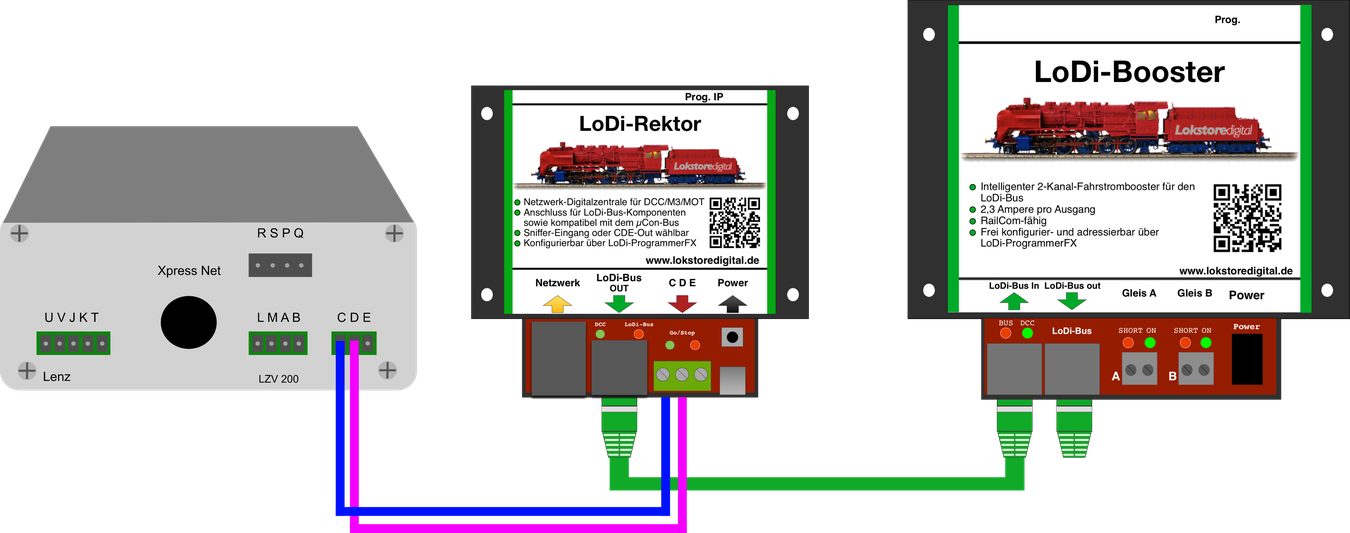
The C D (E) cable should be no longer than 2 metres!
8. The LoDi-Rektor as a booster interface for conventional command stations
The market is full of command stations, and as a customer it is genuinely hard to keep an overview. In principle they all do one thing alike: they are meant to control your trains and/or turnouts. There are all sorts, from high-end units down to small USB sticks.
But there really are command stations on the market that have no C D E connection.
Do they have to stay outside, then?
No! Any command station at all can be connected to the LoDi-Rektor — it only has to speak DCC or Motorola.
The question naturally arises why a command station should be connected to the LoDi-Rektor when it is one itself. Quite simply: you know your system and are happy with it, but want the benefits of RailCom and booster logic.
Or perhaps you have grown so used to your handheld controller that you do not want to be without it.
That is exactly where the sniffer-in comes in — carry on using your old command station as a handheld controller.
Every command station has a track output to which you can connect your track.
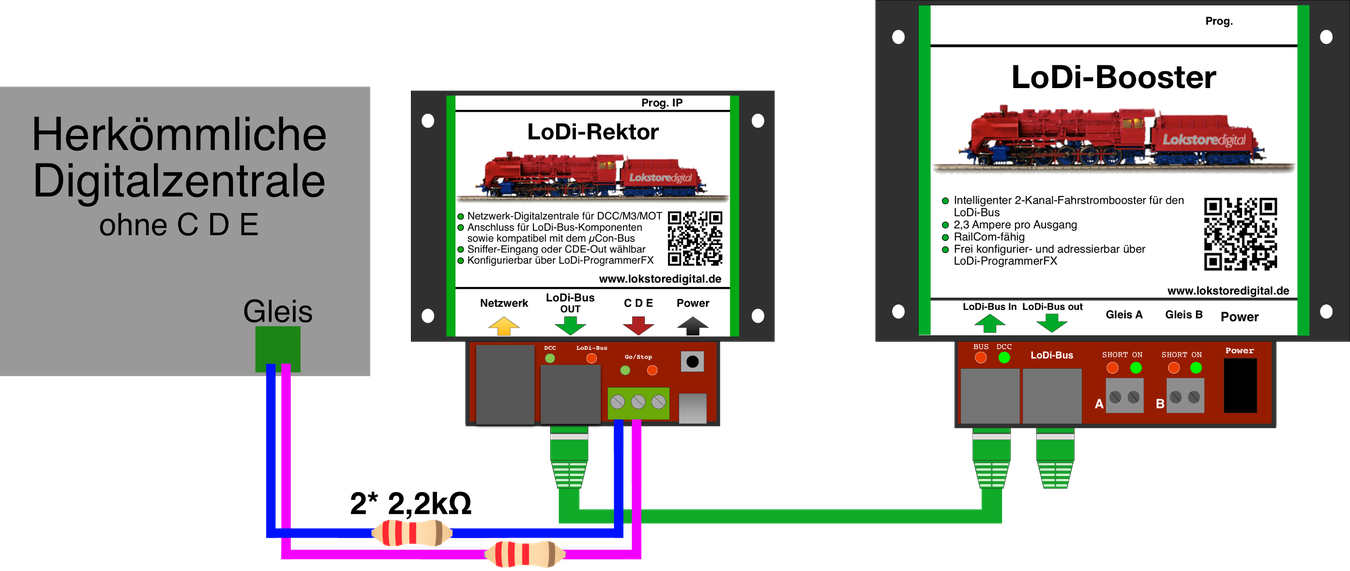
It is of course not possible to connect that track output straight to the LoDi-Rektor.
Two resistors of 2.2 kΩ each have to be inserted into the line for that, as the picture below shows.
That way almost every command station can be connected to the LoDi-Rektor. Use your station as the main command station, or only as manual control through the sniffer-in.
The sniffer-in can only be used from hardware version 6/23 onwards. See the thread in the forum.
9. Technical data
| Property | Value |
|---|---|
| Dimensions | Length 8.9 cm |
| Width | 10 cm |
| Height | 3.5 cm |
| Weight | 89 grams |
The USB-C connection can be powered from any common USB-C cable or power supply.
The maximum load of the USB power supply may be up to 3 amperes.
10. Setting up the LoDi-Rektor in the LoDi-ProgrammerFX
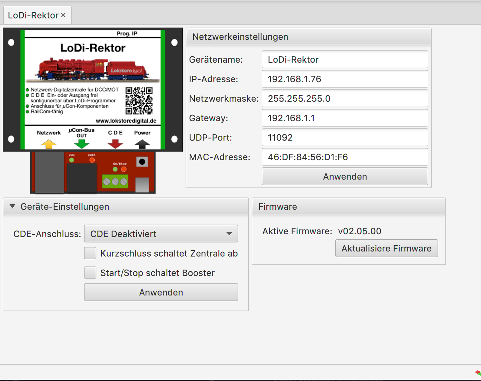
Here is how to commission the IP address of the LoDi-Rektor
Here is how to set up the LoDi-Rektor
11. LoDi-Rektor PDF download
Here you can download a summary of the LoDi-Rektor hardware and software as a PDF.