
Hardware
LoDi-8-GBM v2
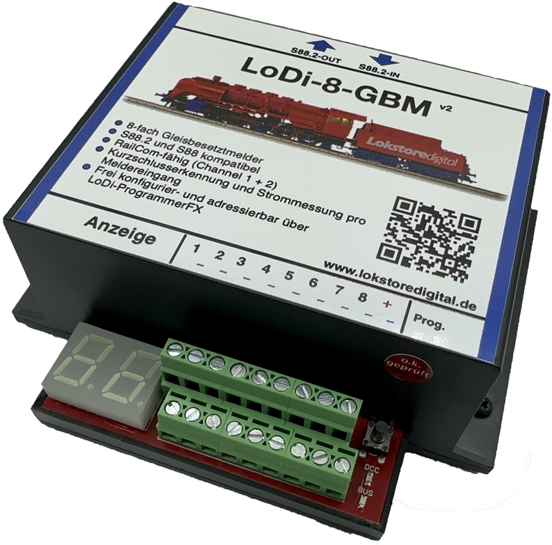
Update late 2022:
Our LoDi-8-GBM gets a small update too: the LoDi-8-GBM v2. It is now fully updatable and prepared for DCC-A.
Introducing: our new occupancy detection module — the second component of our new feedback system, which has already proved itself very successfully on layouts from small to very large. Simplicity of setup and of monitoring are what count here.
With the new S88.2 standard and unconditional RailCom compatibility we offer a new dimension of certainty: where there was once only hope, there is now sure knowledge of where the vehicles actually are on the layout.
Features of the LoDi-8-GBM v2
- The LoDi-8-GBM v2 is an occupancy detector developed for the S88.2 bus.
- It serves 8 track sections, each of which can carry 3 amperes.
- All 8 track sections, that is detection channels, are RailCom capable and can be monitored over channels 1 and 2. (With channel 2 a maximum of 8 locomotives can be identified in a detection channel.)
- Beyond that the occupancy detector also delivers a precise current draw per track section, and can even detect short circuits within the block itself.
- Universally usable with two-rail and three-rail track systems.
- The LoDi-8-GBM v2 is easily configured through the LoDi-ProgrammerFX.
- A display for checking the detectors directly and showing the module's address.
- Fully backwards compatible. The LoDi-8-GBM v2 can equally be run on s88N and, with an adapter, on an old s88 bus. There you will not have the full functions of the S88.2 bus, however.
1. The LoDi-8-GBM v2 and its connections
About the connections on the LoDi-8-GBM v2:
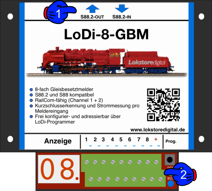
- (1): the S88.2 bus connects here. The S88.2-OUT arrow points towards the interface, since this is where the data from the track is reported back to the computer. The LoDi-8-GBM v2 is of course s88N compatible too; you can simply integrate it into existing layouts, but will then not have all the benefits of the new S88.2 bus.
- (2): the block sections, or detection sections, connect at 1–8 here, and the booster IN voltage to their right at +. You will find more under track connection below.
2. The LoDi-8-GBM v2 and its LEDs
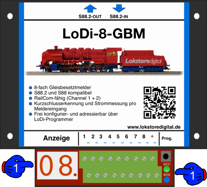
- (1) DCC LED and BUS LED: the bus LED lights as soon as the S88.2 bus is plugged in and supplied with power. The bus LED then glows a light blue. The DCC LED lights as soon as booster voltage is present at the module.
- (2) Display: during operation this shows the detector currently occupied. The dot to the right of the number shows whether the module has detected the bus.
3. Connecting the LoDi-8-GBM v2 to the S88.2 bus
As mentioned several times, the LoDi-8-GBM v2 carries the new S88.2 bus. That is provided by the LoDi-S88-Commander FX. You can connect up to 96 LoDi-8-GBM v2 units to one LoDi-S88-Commander FX.
When the module is run on an S88.2 bus, the following features are available to you:
- Occupancy reporting of the individual blocks with a display
- Short-circuit detection for the individual blocks. This works through a further register, which means: should a short be detected on output 1.1, for instance, 1.9 is reported as occupied. The short can therefore already be displayed by any control software.
- Current measurement per detection channel, with the option of displaying it in the software.
- Setting the short-circuit thresholds per detection channel.
- Setting the current detection threshold per detection channel
- RailCom detection on channels 1 and 2 per detection channel (max. 8 locomotives per detection channel).
- Freely addressable — the module now keeps its address, there are no more shifts!
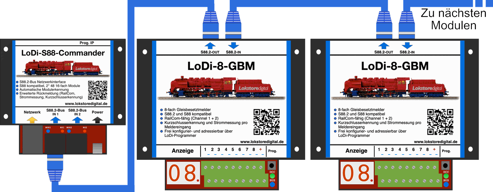
4. Connecting the LoDi-8-GBM v2 to the s88 and s88N bus
The LoDi-8-GBM v2 is fitted with the new S88.2 bus, which does not mean the module cannot also be run on conventional command stations with s88 or s88N.
These functions are available to you when running on the old s88 bus:
- Occupancy reporting of the individual blocks with a display
- Short-circuit detection for the individual blocks, here through a further register, which means: if a short is detected on output 1.1, for instance, 1.9 is reported as occupied. The short can therefore already be displayed by any control software.
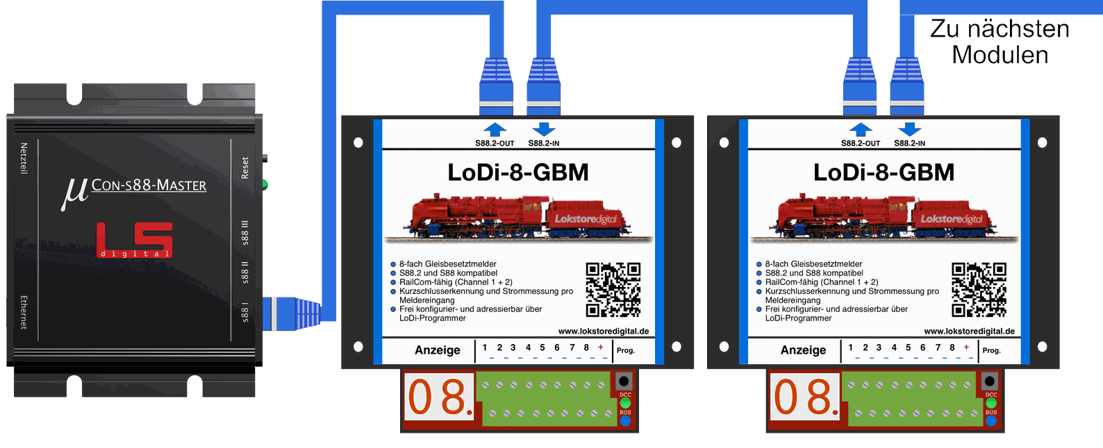
Here you see a LoDi-8-GBM v2 connected to a µCon-s88 master. It makes no difference whether the LoDi-8-GBM units are connected to bus 1, 2 or 3; they behave like perfectly ordinary s88 modules.
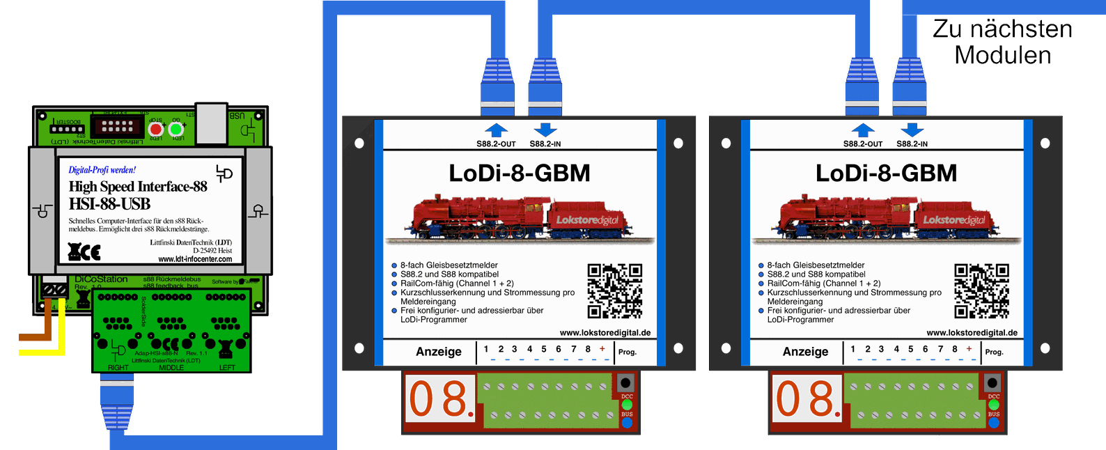
Here you see a LoDi-8-GBM v2 connected to an LDT-HSI. Any kind of s88N module can of course be hung in between.
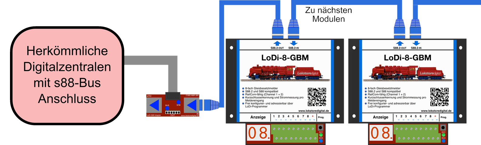
It is possible to connect the LoDi-8-GBM v2 to a conventional command station. To use the devices on an older station without the s88N connector, you need an adapter.
We offer the LoDi-S88 adapter for that, which can be used universally
5. Connecting booster voltage to the LoDi-8-GBM v2
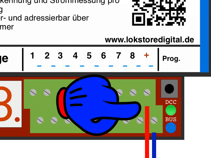
The LoDi-8-GBM v2 has a booster input terminal. A booster or a conventional command station has to be connected to it.
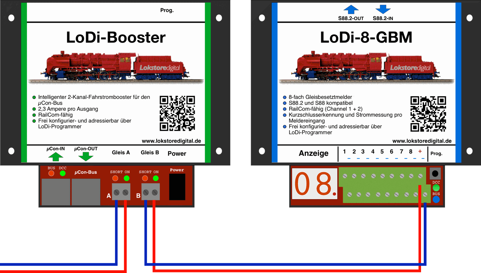
The first example shows the LoDi-Booster supplying the LoDi-8-GBM v2 with power.
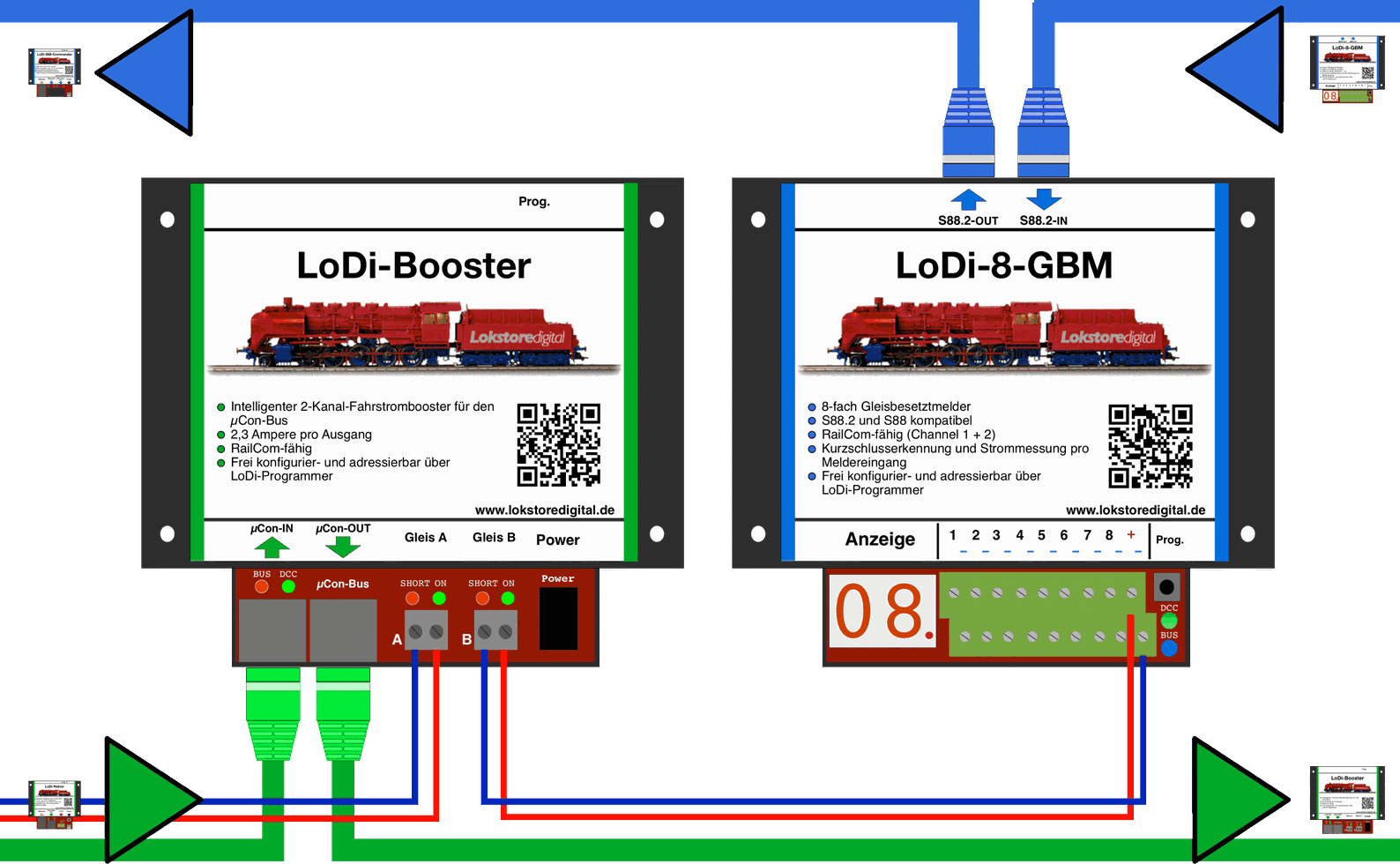
Please take care that the red wire, that is the + connection, is connected to the right-hand booster terminal at outputs A and B respectively. If the red wire is on the other side, it can affect the RailCom signal.
A complete view, in which the modules' buses are now shown as well.
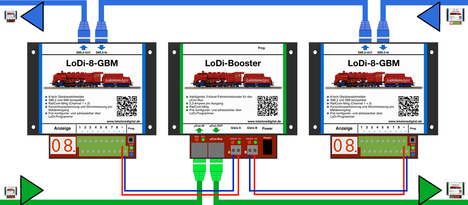
Your wiring might look like this, for instance. You can of course also have several detection modules supplied from one booster section.
6. Connecting the LoDi-8-GBM v2 to two-rail track
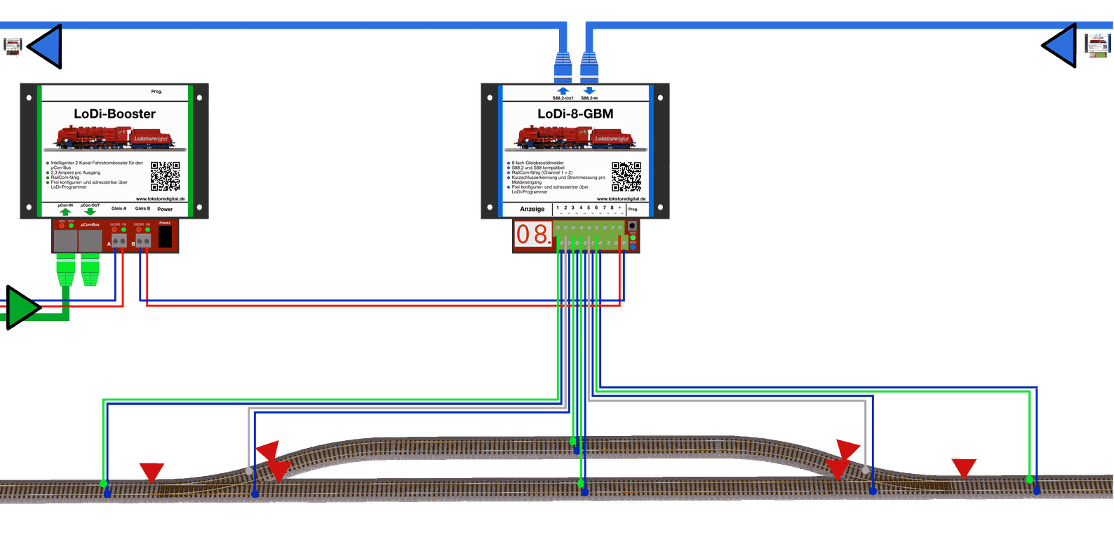
Occupancy reporting for two-rail track is easy to arrange with the LoDi-8-GBM v2, always depending on how many detection sections your control software needs.
In our diagram we assume one detector per block; entry and braking detectors could of course also be needed or wanted. If you are interested in the cable colours we use, click here under "Useful information"
7. Connecting the LoDi-8-GBM v2 to three-rail track
The three-rail system is very widespread among modellers. That is exactly why three-rail operators matter to us. With the LoDi-8-GBM v2 it is possible to run MFX® and DCC on one track.
What advantages does that bring?
- Vehicle position accurate to the detector or block
- You place a locomotive on the track, the computer detects it and puts the locomotive into the block automatically.
- Monitoring of the route
- Short-circuit reporting accurate to the detector
- Current draw accurate to the detector
All the locomotive needs for that is a RailCom transmitter. If you already have another decoder in the locomotive that can do DCC, you can run it in DCC directly.
Most decoders on the market handle RailCom.
One more note: Motorola has to stay outside here. If you do not want to do without Motorola, you have to use the conventional solution with common reporting.
We developed the LoDi-RM-16+ for that; it even offers a common return to the track (the diode trick).
Do note, however, that with this version of the LoDi-RM-16+ no locomotive-specific reporting can be evaluated.
If you have questions about that, do contact us.
First of all let us look at the wiring of the three-rail layout.
It takes a little rethinking, which we explain briefly here: (a similar explanation can also be found under LoDi-Booster, section 7)
Imagine the centre rail simply becoming the common. Since the common on the layout may always be one, you do not have to separate the new common either.
Which means the centre rail is always joined throughout.
If you have already separated the centre rail on an existing layout, it can be joined again, or you can run the booster sections with the common separated.
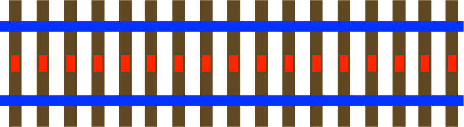
Here you see the normal standard method used with three-rail.
So the centre rail, RED, is B; the common rails above and below, BLUE, are O
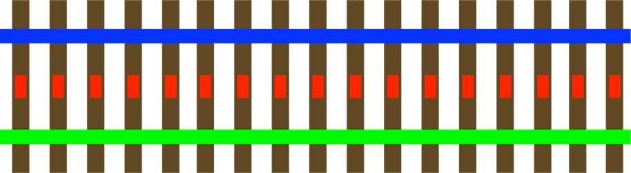
In this example you see the upper side carrying the common, here BLUE, that is O.
The centre rail stays RED, that is B.
The lower side of the track is now the detector for the common report, that is GREEN, as has been usual for reporting with the three-rail method
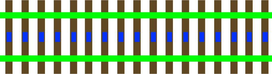
So that the locomotive's RailCom data also reaches the control software per block, we have to route the current through the LoDi-8-GBM, which is used for this application in the three-rail method.
It takes a little rethinking, but we know from numerous customers that this solution works perfectly.
Occupancy reporting for three-rail track is easy to arrange with the LoDi-8-GBM v2, always depending on how many detection sections your control software needs.
In our diagram we assume one detector per block; entry and braking detectors could of course also be needed or wanted. If you are interested in the cable colours we use, click here under "Useful information"
Here we have separated the track on the right and left and left the centre rail joined. With this variant the fishplates on C track, for instance, do not have to be separated. In this variant, however, only current-drawing items are detected, meaning only locomotives or coaches with a pickup shoe.
Another variant is wagon detection. That means a report is produced as soon as you place a wagon in a detection area. For that, though, we have to separate the connection from the left to the right rail, as with C track.
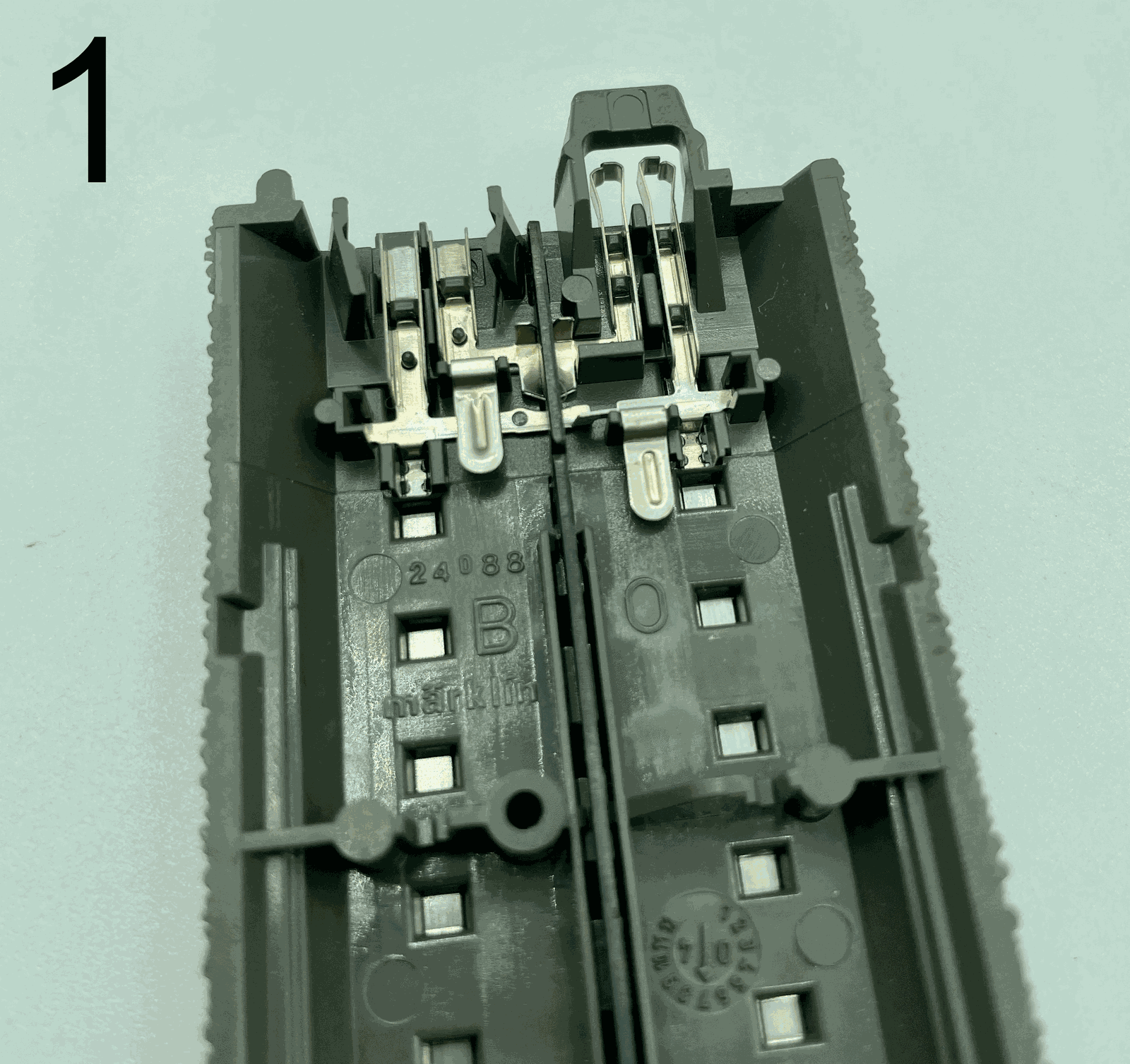
In pictures 1 and 2 you see the connection in C track, contacted from the right to the left side on the underside of the track.
In picture 3 we put a small pair of side cutters to the right-hand fishplate 0. The connection can be severed there.
In picture 4 you see the connection severed. When separating, take care that both sides have to be separated from the track. It is worth having a voltmeter in the house for this. A continuity tester can show you that the right side really is separated from the left.
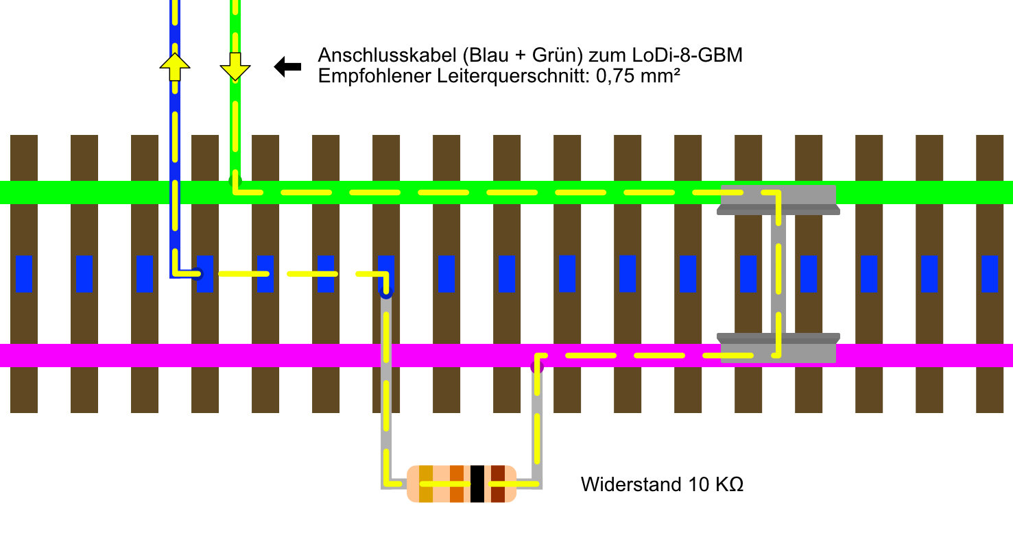
Both sleepers in a block are still isolated, but a resistor of 10 kilohms is now fitted between the centre rail, that is the common (blue), and the non-current-carrying sleeper, in purple.
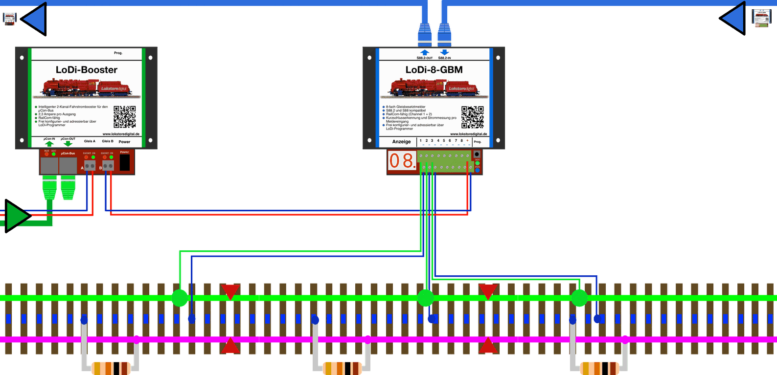
Here is another example picture in which a long single-track stretch has been divided into several blocks or detectors. A resistor is now fitted in each section.
The turnouts are not separated; as shown in the diagram above, they are simply wired in as well.
Turnouts are not separated. In principle it can be done with some effort, but we advise against it.
So if you have decided on the variant with the resistors, the question remains how occupancy of the turnout can be monitored.
Let us explain that here: the turnouts do not have to be cut or the fishplates separated. It is technically possible, but laborious and inadvisable, since we would have to take one side of the common away from the turnout. For smaller locomotives in particular that does not help contact, so the rails of the turnout stay joined.
The turnouts should nevertheless always be reported. Most accidents and derailments happen on turnouts. Here the LoDi-8-GBM can show precisely, through its short-circuit detection in the control software, where a short has occurred. A train running the wrong way can also be spotted at the turnout.
We explain that here with the diagram: (all pictures can be enlarged by clicking.)
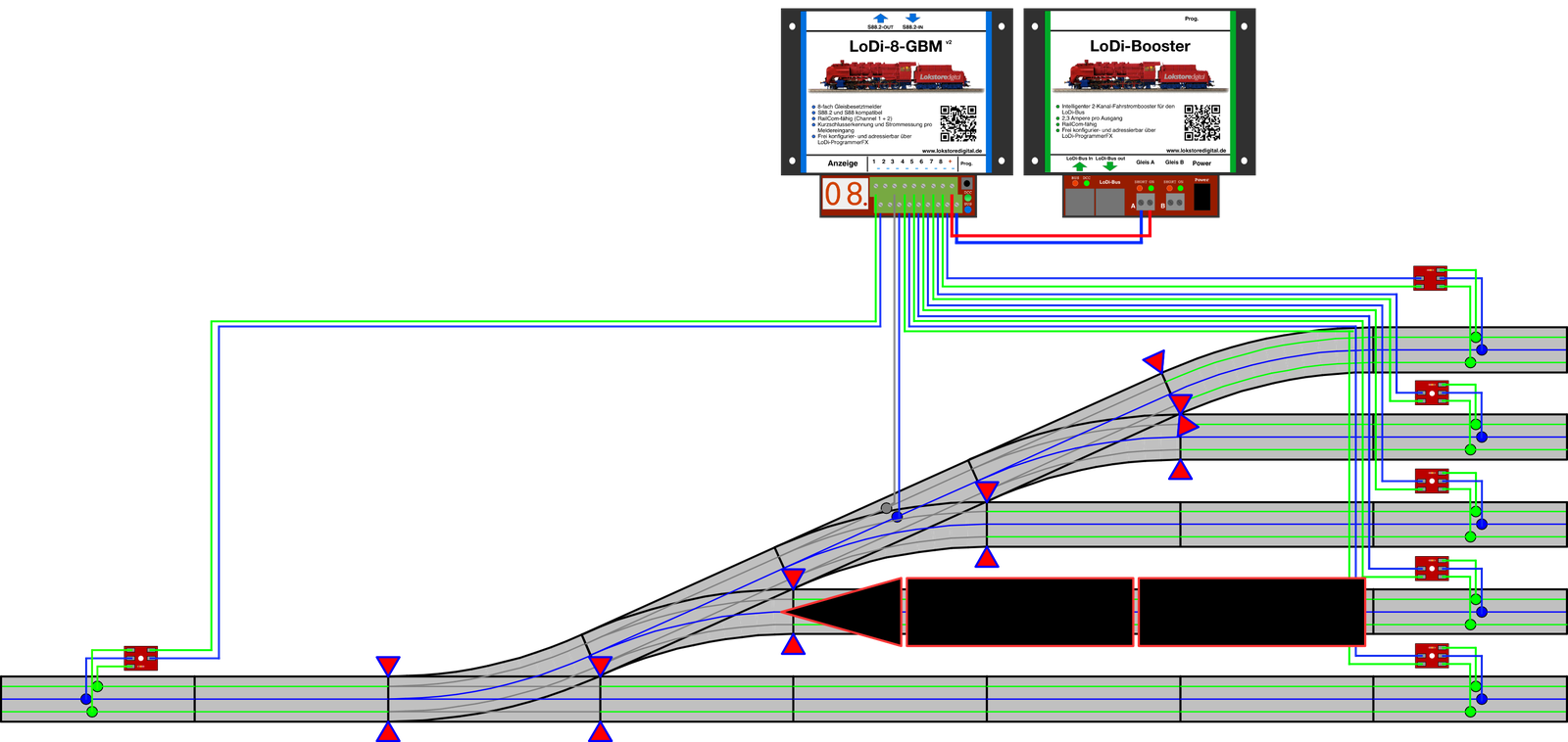
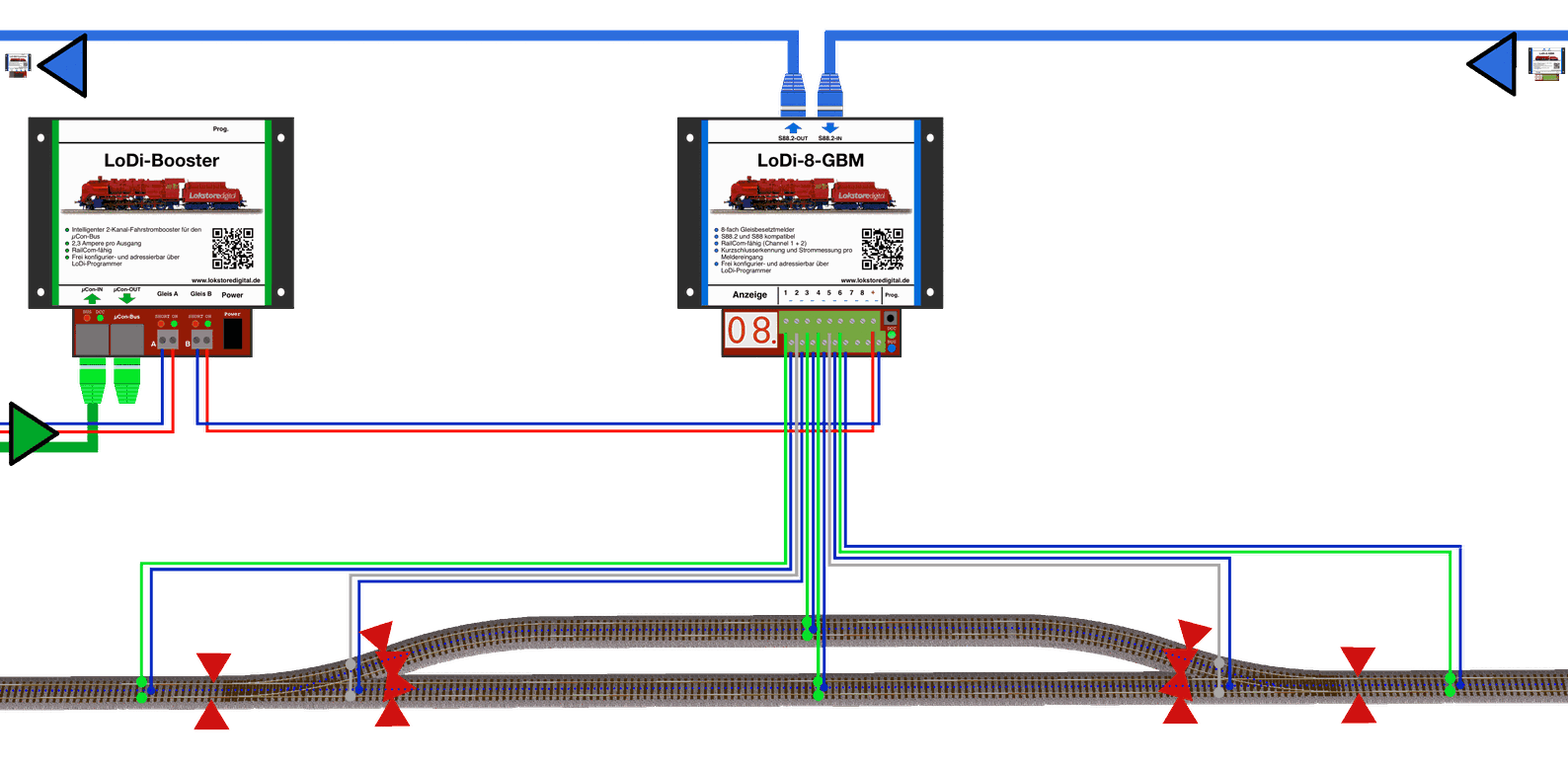
This example shows a five-road station leading out onto one track.
All four turnouts can be put on one detector here, since only one locomotive or train can ever be on the route at a time.
So the general rule is: if a route ends on a single-track stretch, the turnouts can be combined onto one detector.
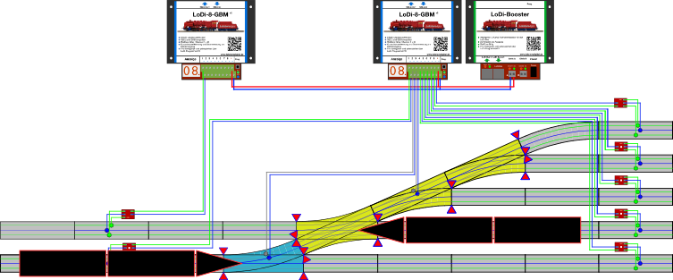
Things look different when two or more trains can run over a route.
Then, if you run with RailCom, the route has to be divided so that the paths across the turnouts are separated from one another. In the example here we see the lower turnout in BLUE. It gets a detector of its own. A train could run straight ahead without affecting the double slip or the upper turnouts. That double slip can now serve the attached turnouts with one detector. Here the rule applies again: only one train can run out over the upper turnouts and the double slip.
If you are unsure how best to divide up the routes, contact us or our partners. We will gladly help.
8. Technical data
| Property | Value |
|---|---|
| Dimensions | Length 130 cm |
| Width | 115 cm |
| Height | 4.5 cm |
| Weight | 169 grams |
! ! ! Careful ! ! ! The S88.2 bus may only be run at 5 volts. Do therefore check what voltage your S88 bus runs at. ! ! ! Careful ! ! !
At the digital terminal the detector can be supplied with 12 to 24 volts.
Do mind the specifications of your command station or booster manufacturer here.
Loadable by consumers with 5 amperes briefly and 3 amperes continuously per output.
Suitable for every common scale.
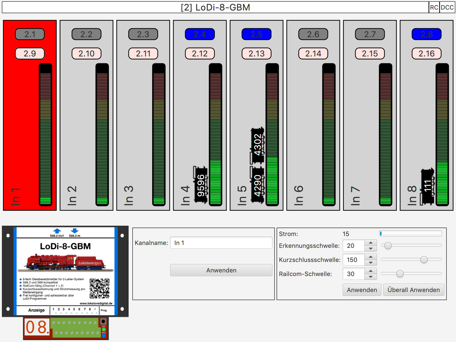
9. Setting up the LoDi-8-GBM v2 in the LoDi-Programmer
Here is how to set up the LoDi-8-GBM
10. LoDi-8-GBM PDF download
Here you can download a summary of the LoDi-8-GBM hardware and software as a PDF.