
Hardware
LoDi-83-AC
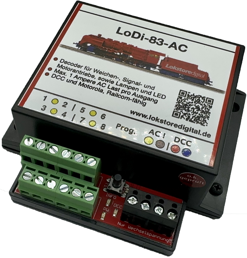
Inspired by our LoDi-Operator 4-WD-AC, we designed the LoDi-83-AC for the DCC signal.
The advantages of switching with AC, simply in one decoder with 8 outputs that can drive up to 4 turnouts.
It is RailCom-capable and can be programmed live on the track. No more tired drives, thanks to true AC at the output.
Features of the LoDi-83-AC
- An AC decoder for the DCC and Motorola protocols.
- Eight channels are available, each with 1 ampere per output; the total of the connected channels must not exceed 2 A.
- You can connect all common motor turnout drives, solenoid drives and lamps to the LoDi-83-AC.
- The LoDi-83-AC is equally suitable for loads that require AC, such as stopping sections, other old coils or universal motors.
- It demagnetises drives with coils!
- Every output is separately protected against overload.
- Easily configured over DCC RailCom.
The LoDi-83-AC and its advantages — the LoDi-83-AC demagnetises the iron armatures in your drive's coils.
Why is that?
Picture an ordinary decoder from one of the usual manufacturers.
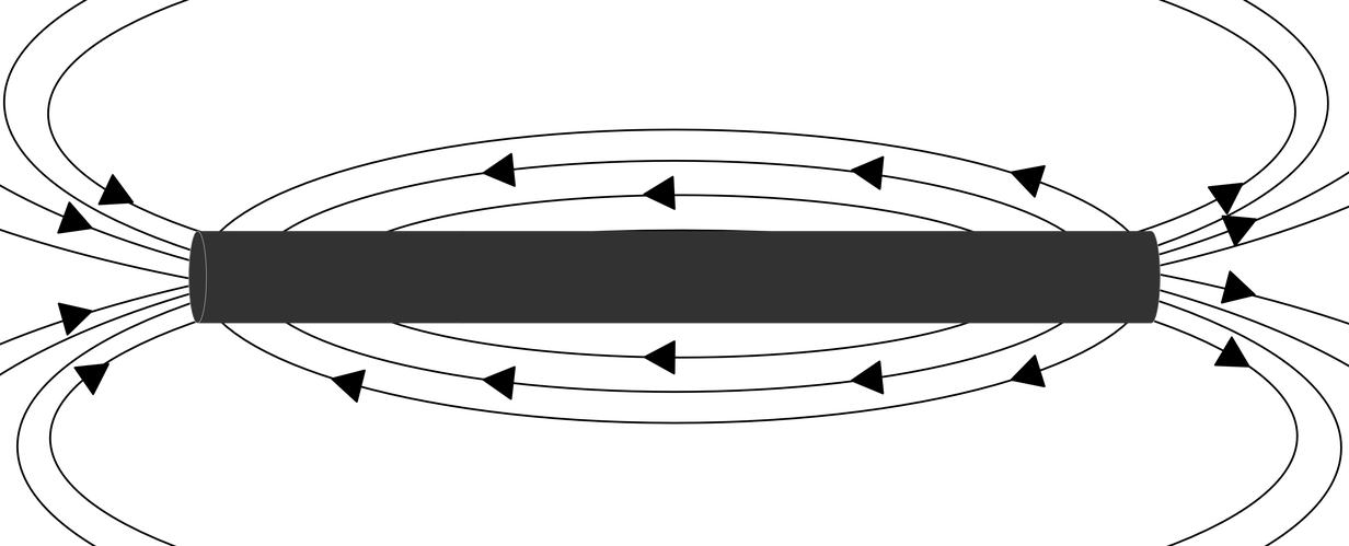
It always switches with DC, which means the iron armature is gradually magnetised by that DC. This is known as magnetic remanence. The consequence is that the armature can no longer be switched reliably by the coils, because their magnetic field is no longer strong enough.
The decoder, or rather the drive, becomes unreliable.
The principle of a twin-coil drive
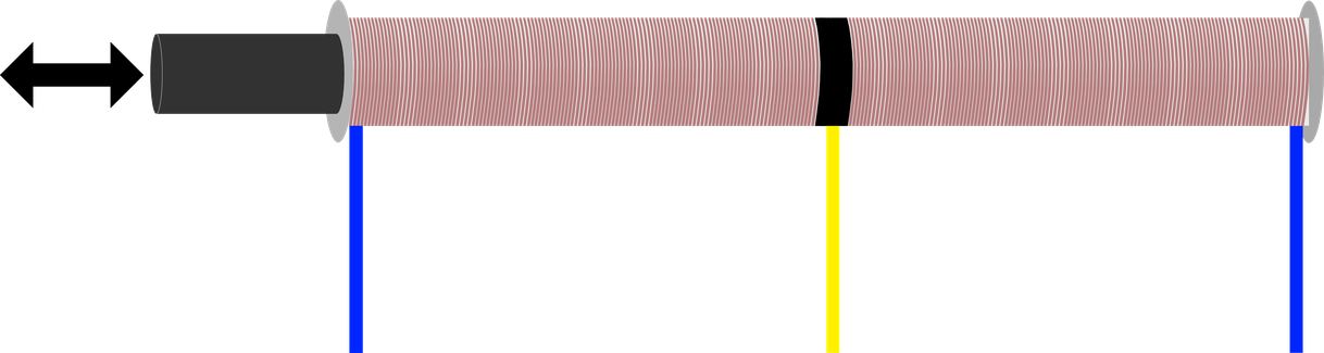
The iron armature of a twin-coil drive with remanence
The iron armature of a twin-coil drive without remanence
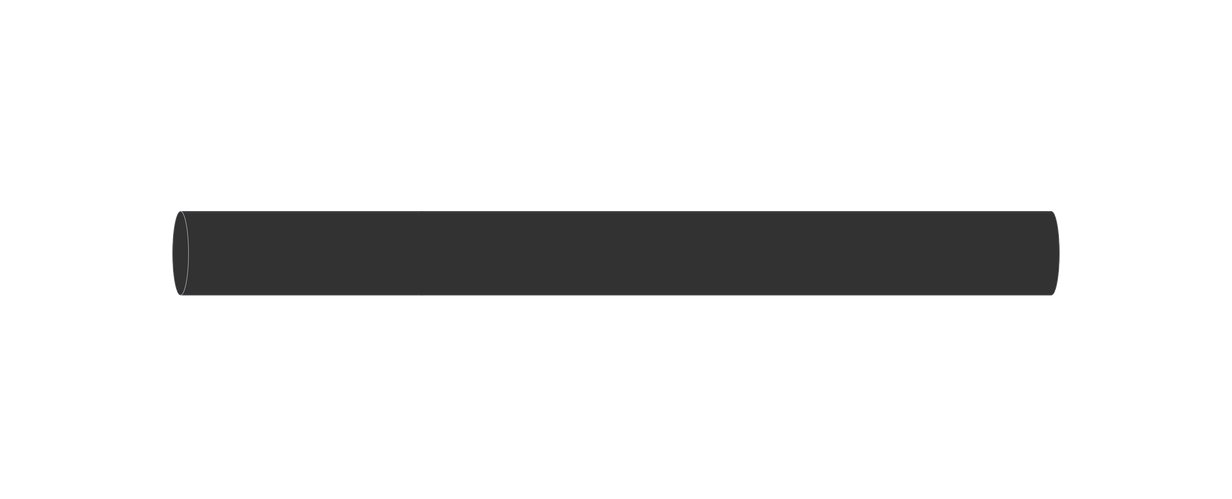
We developed this decoder to rule that effect out. It only passes AC through. That prevents magnetisation, because no lasting remanence can build up.
Your drives therefore keep switching at full strength.
Videos about the device from YouTubers
Here we show contributions from customers who use LoDi devices and have taken the time to create tutorials.
1. The LoDi-83-AC and its connections
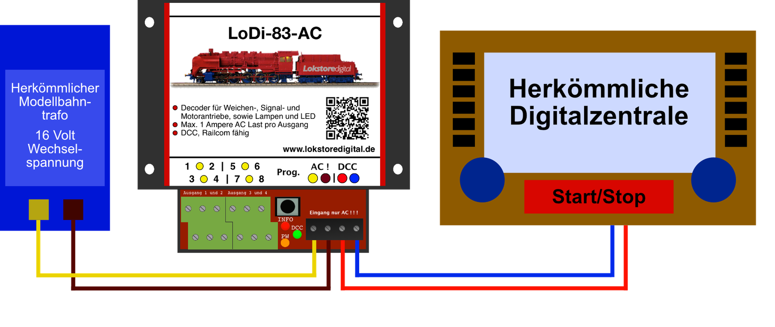
The LoDi-83-AC is connected to a digital command station for the data signal and to a transformer for the switching power supply.
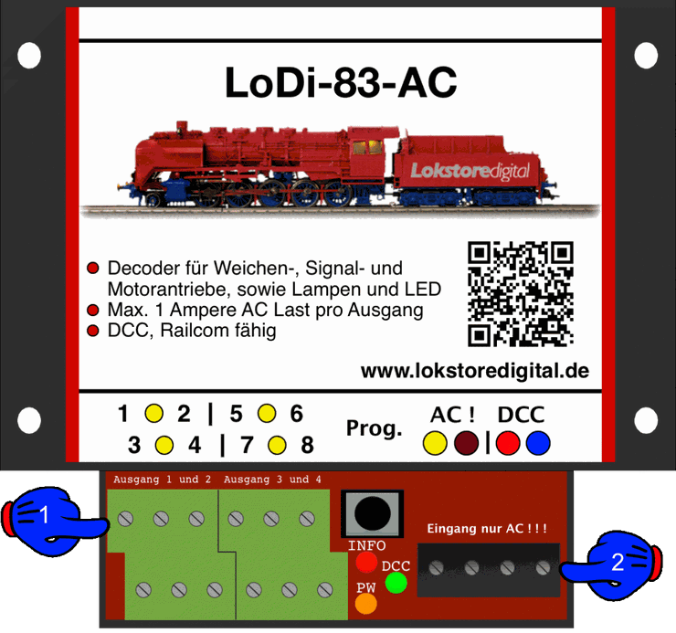
About the connections on the LoDi-83-AC
- (1) Here you can connect the loads, turnouts, lamps and so on; you will find more on this in the wiring examples further down.
- (2) The AC model railway transformer is connected here, at yellow and brown. ! ! ! AC ONLY ! ! ! IMPORTANT! Please only use authorised model railway transformers. The DCC coming from the booster or command station is connected at red and blue.
2. The LoDi-83-AC LEDs and button
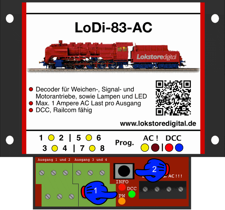
The decoder has three LEDs for status and a button, used to give the decoder an address, for instance.
- (1) The red LED (Info) lights as soon as the decoder receives a signal valid for it, or when RailCom data is sent.
- The green LED (DCC) lights as soon as DCC is present at the decoder.
- The orange LED (PW) lights as soon as the decoder is connected to a transformer. Should there be a short circuit on an output, the orange LED goes out. The LED is also off when the transformer is not connected or is switched off.
3. Connecting a model railway transformer
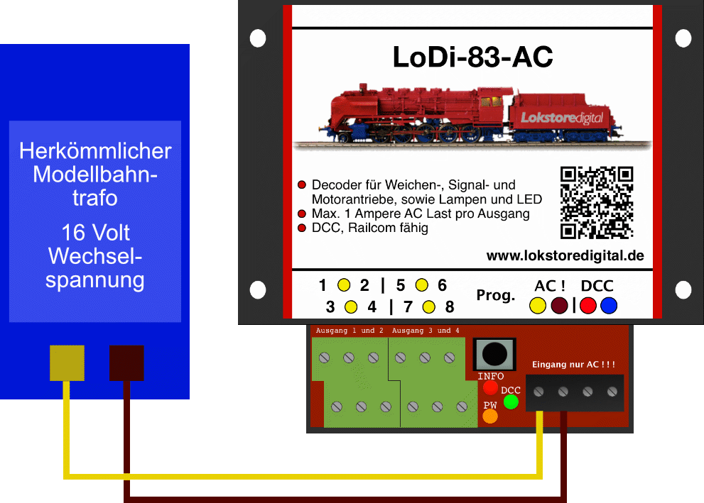
The LoDi-83-AC has 2 terminals for feeding in the model railway transformer. If you want to connect several decoders to one transformer, we can recommend the LoDi-Verteiler series under Accessories.
CAREFUL!
Please do not use cable below 0.75 mm²!
Please watch the polarity of the power supply!
AC ONLY!
4. Connecting a digital command station
Once the decoder is supplied with power, that is E (energy), it has to be able to receive data. For that the decoder should be connected to a command station or a booster.
In the example here we use a LoDi-Booster.
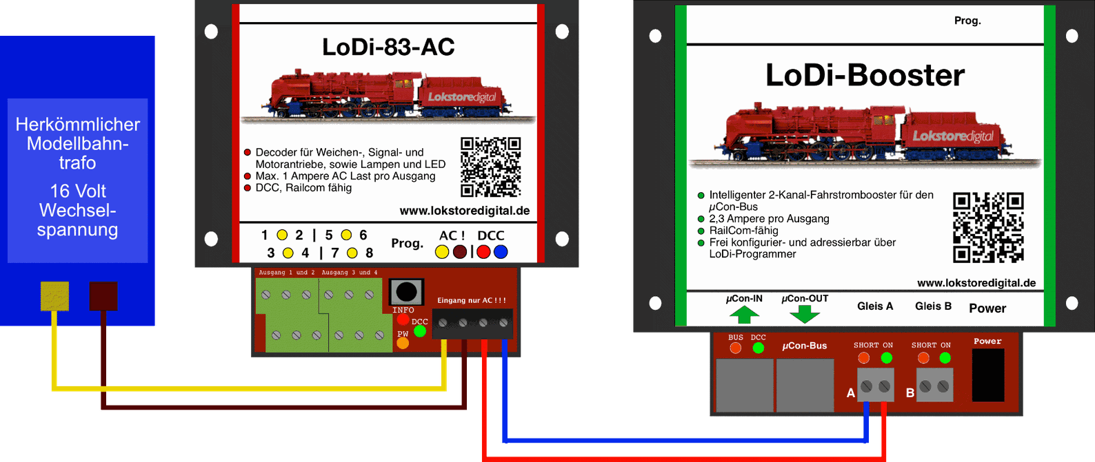
The LoDi-83-AC can be run with any commercially available command station, as long as the station supports the DCC or Motorola signal. We do however recommend running the decoder in DCC where possible. CVs can only be configured over DCC.
CAREFUL!
For reliable switching of DCC accessories, a separate circuit or booster output should be used if one is available.
5. Connecting the LoDi-83-AC to the loads
In the following example you see turnout drives from various manufacturers connected to the LoDi-83-AC.
Drives from a wide range of manufacturers can of course be mixed on the decoder.
Four twin solenoids or motor drives can be connected per decoder.
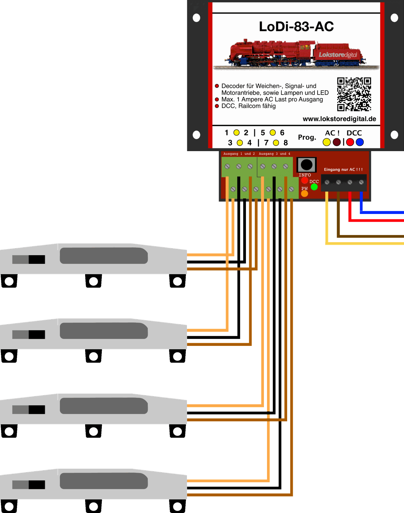
Example with the Märklin® K track solenoid drive
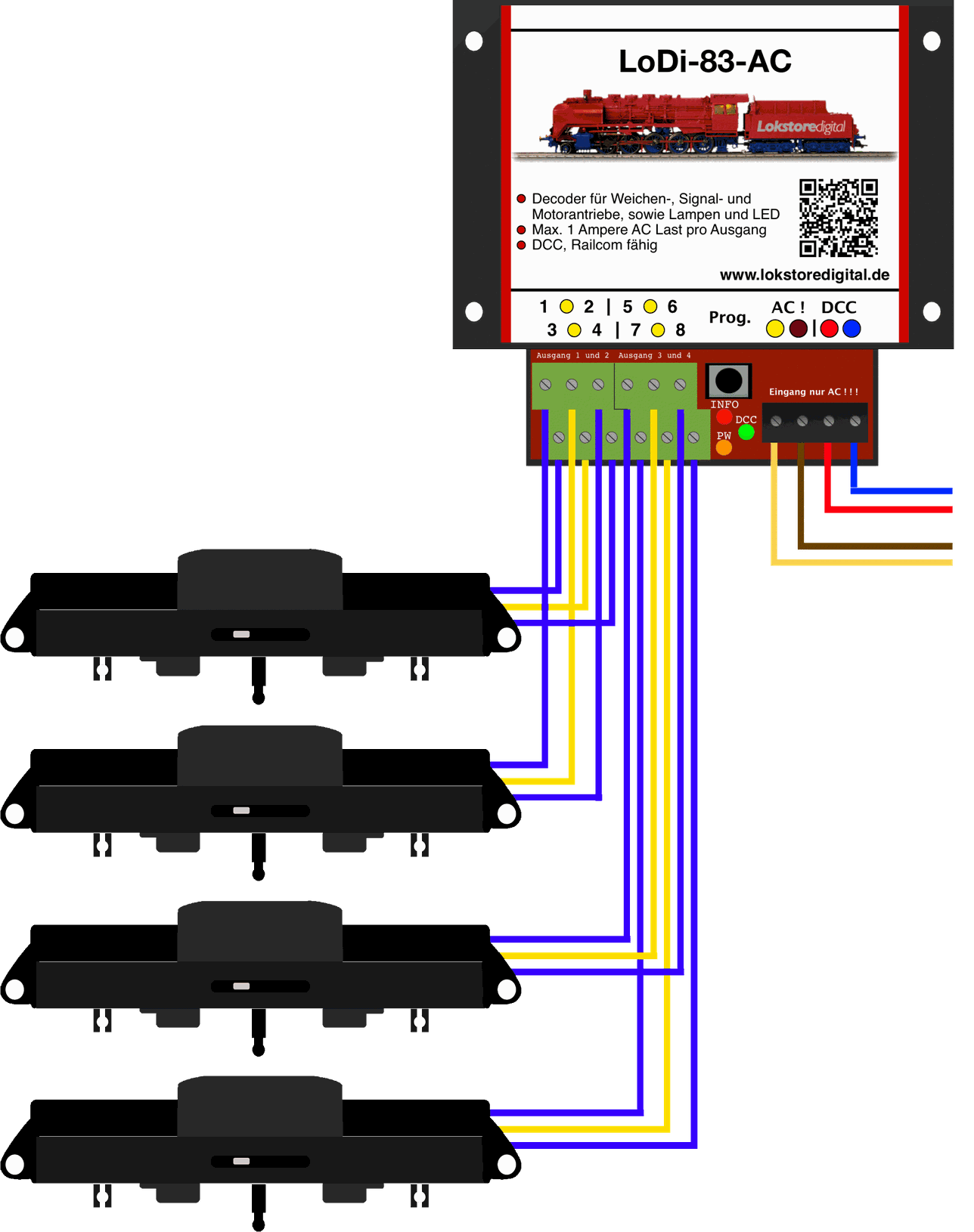
Example with the Märklin® C track solenoid drive
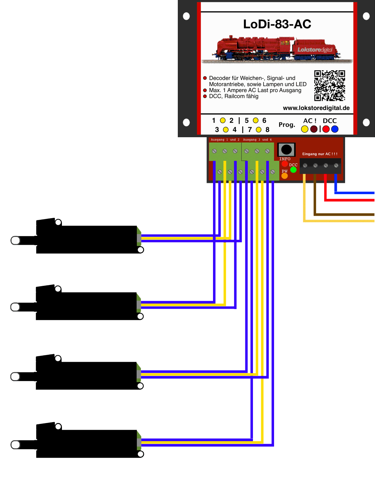
Example with the Piko® solenoid drive
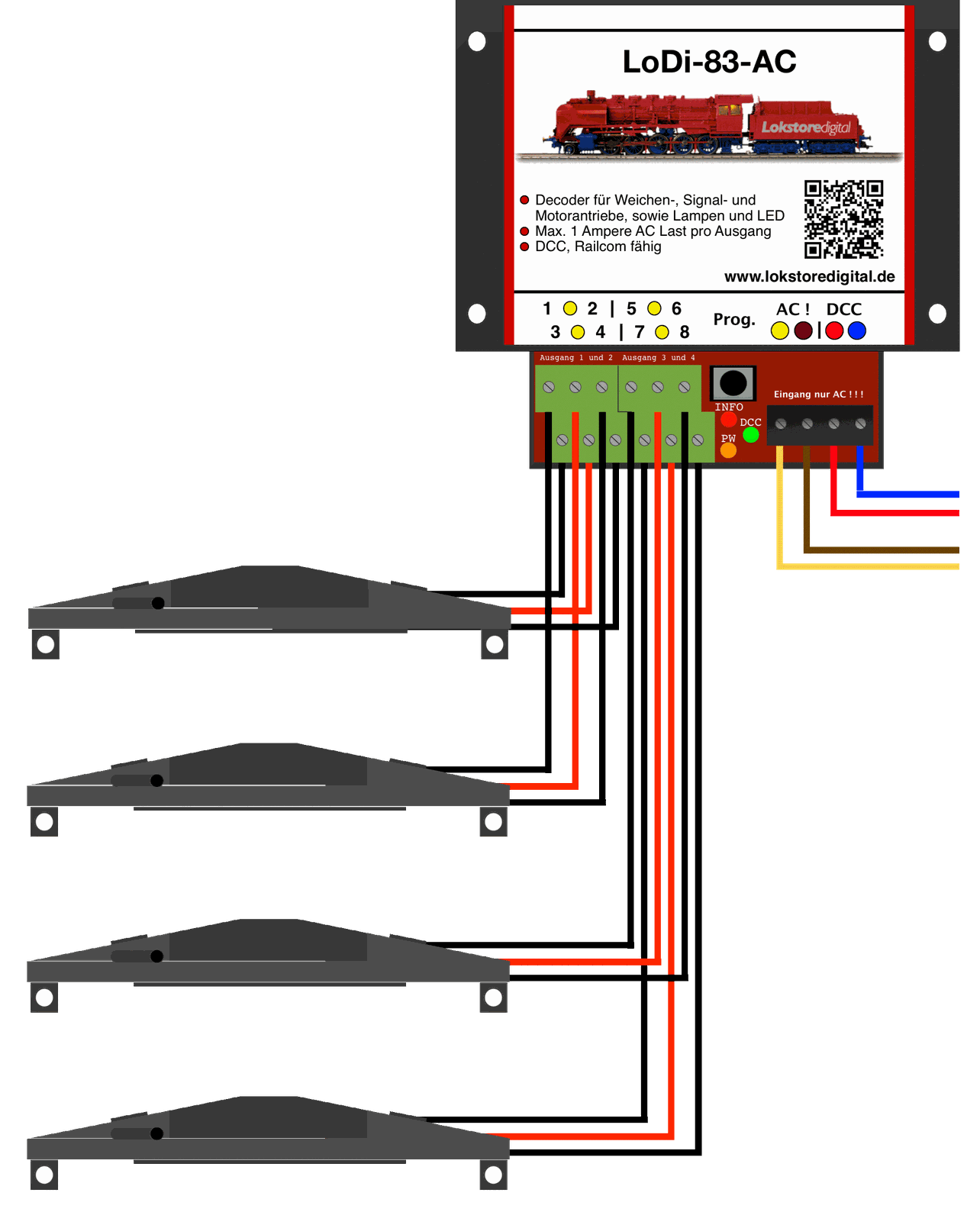
Example with the Fleischmann® solenoid drive
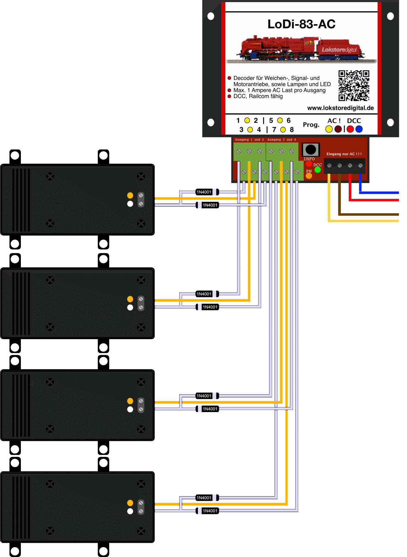
Example with the LGB® motor drive (EPL)
Some motor drives require two diodes; these can be type 1N4001, for instance.
You will be able to get them from us in the shop shortly, or from other electronics suppliers.
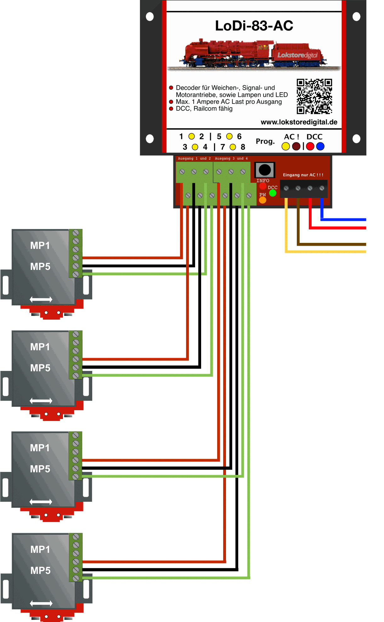
Example with the MTB motor drives (MP1, MP5, etc.)
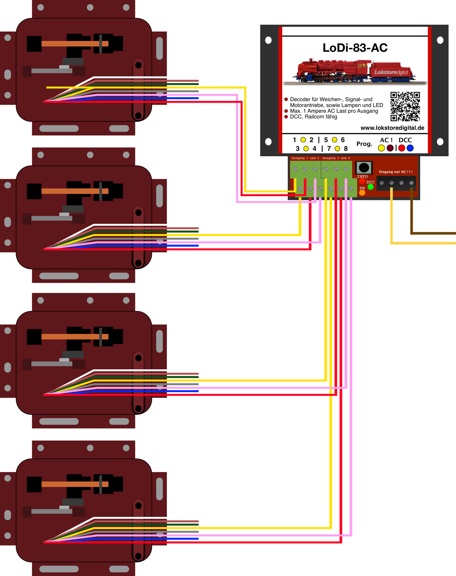
Example with the Tillig motor drives
Further drives that have been tested with the LoDi-83-AC in continuous use.
- The Märklin M track system, including old Märklin signals with coil drives
- Fulgurex motor turnout drives
- Hoffmann motor turnout drives
- Conrad motor turnout drives
- Viessmann signals with solenoid lift drives
Many other drives can be connected to the LoDi-83-AC AC decoder without trouble.
We are happy to extend the wiring example pictures accordingly.
If a drive you use is missing, do let us know.
6. CV list, settings, addressing
The LoDi-83-AC is set through CVs.
If you have the LoDi-Rektor with a LoDi-Booster or CDE booster connected, you can write the CVs over PoM (programming on main) with the LoDi-ProgrammerFX from version 2.2.
The decoder can equally be programmed with any conventional command station that has a DCC programming output or handles PoM.
If you have a RailCom capable system, you can read the decoder's CVs live at any time.
Setting the data format in the LoDi-83-AC
You have now installed the decoder successfully, the power and data cables are plugged in, and the LoDi-83-AC glows orange continuously to show it is ready.
The green LED lights as soon as a DCC signal is present at the DCC terminal.
As delivered, the LoDi-83-AC is set to DCC. To switch the decoder to Motorola, proceed as follows: press the Prog button (2) briefly; the red "INFO LED" (1) now glows steadily. Now press the button again and hold it until the decoder restarts. It is now set to Motorola. If you want to switch the decoder back to DCC, repeat this step.
Setting a DCC or Motorola address: as delivered, the decoder responds to turnout or accessory addresses 1–4.
If you want to change an address quickly, proceed as follows: there is a prog. button (2) on the decoder. Press it for 3 seconds.
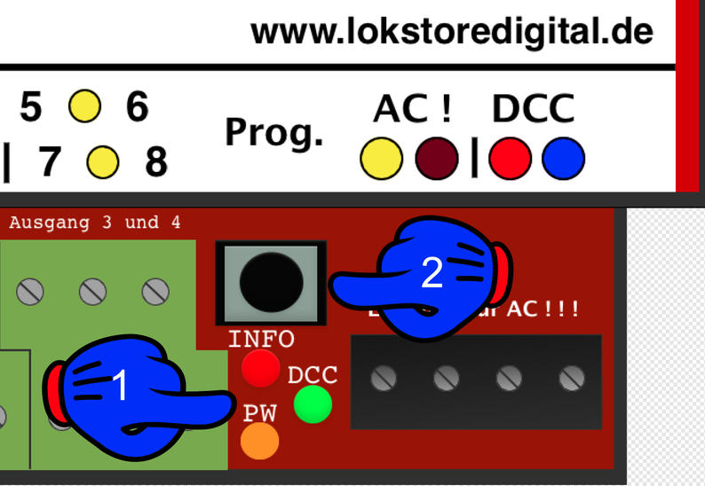
The info LED (red) (1) starts to flash quickly. That is the decoder telling you it is ready for a new address.
Now send the new address from your command station, from your model railway control software or from the LoDi-ProgrammerFX (the LoDi-Rektor is required).
The decoder takes the address and the info LED stops flashing. It is now reachable at the address you chose. Only the first address has to be sent. All three further addresses are assigned automatically. With 1, for instance, 1–4, and so on.
Setting the CVs: as mentioned several times, the LoDi-83-AC can be programmed over PoM (programming on main).
Let us assume you have a motor turnout, an MP1 for instance, connected to output 1, that is 1+2.
On the other outputs there are ordinary solenoid accessories such as Märklin drives.
The first pair of outputs is now to be given a longer switching time.
First go to the programming menu of your command station, model railway software or the LoDi-ProgrammerFX.
Now select the decoder's address.
CAREFUL!!!
Only the decoder's first accessory address may be selected. This means that if the decoder listens on addresses 1–4, only the first address of the decoder may ever be used; that is the address at which the station reaches the decoder and can programme it.
In this case address 1.
Now send the value 70 for CV51 (this is output pair 1). The decoder now works for about 2.5 seconds per output. That is enough time to drive the MP1.
Now we also want to give the Märklin drives on outputs 2–4 a longer switching time. The default is 15, which is 375 ms. We now raise that value for output pairs 2, 3 and 4 in CVs 52, 53 and 54 to 30.
The drive is therefore switched on for 750 ms.
These values can be read back later over RailCom.
7. Setting up different loads on the LoDi-83-AC
As described several times, the LoDi-83-AC can drive or switch any universal motors, lamps, solenoids, stopping sections and much more.
Let us assume you still have outputs free on a decoder, or want to use the outputs directly for switching other loads instead of turnouts.
That gives us 8 outputs, which can then be switched over 8 DCC addresses.
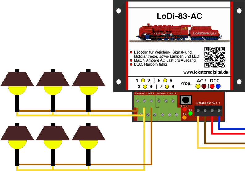
In this example we have now connected several lamps to the first and to the second output.
Since these are now connected to the first output pair, that is 1 and 2, we now have to tell the decoder through a CV that these outputs are to be split and can be driven as their own addresses.
To do that, send a 0 in CV51 (the first address pair) to decoder address 1, which is the address in our example.
The lamps can now be switched separately with turnout addresses 1 and 2.
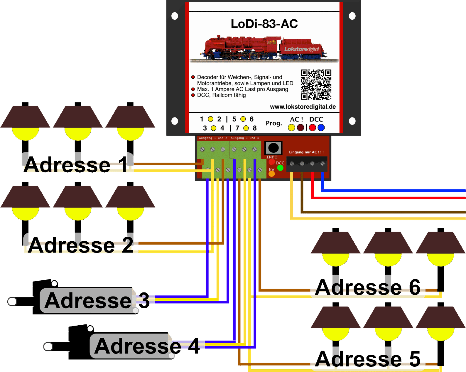
Let us look at the example shown here a little more closely.
On outputs 1 and 2 you see connected lamps, as shown in the picture. So we have to set CV51 to 0. That now means outputs 1 and 2 can be switched on and off over DCC addresses 1 and 2.
On the next output pair we now have a turnout drive; we leave CV 52 at the value 15, which means this turnout is reachable at address 3.
The third output pair also stays unchanged and has address 4.
On the fourth output pair we have again installed 2 lamps.
So here we set CV 54 to 0. These lamps therefore now need DCC addresses 5 and 6.
This can be applied to up to 8 DCC addresses.
8. Technical data
| Property | Value |
|---|---|
| Dimensions | Length 8.9 cm |
| Width | 10 cm |
| Height | 3.5 cm |
| Weight | 97 grams |
At the digital terminal, that is in digital operation, the decoder can be supplied with up to 22 volts.
Do mind the specifications of your command station or booster manufacturer here.
The decoder must be powered with AC!
Permitted from 12 to 24 volts AC.
Loadable by loads with 3 amperes briefly and 1.5 amperes continuously in total.
9. LoDi-83-AC PDF download
Here you can download a summary of the LoDi-83-AC as a PDF.