
Hardware
LoDi-Watchdog
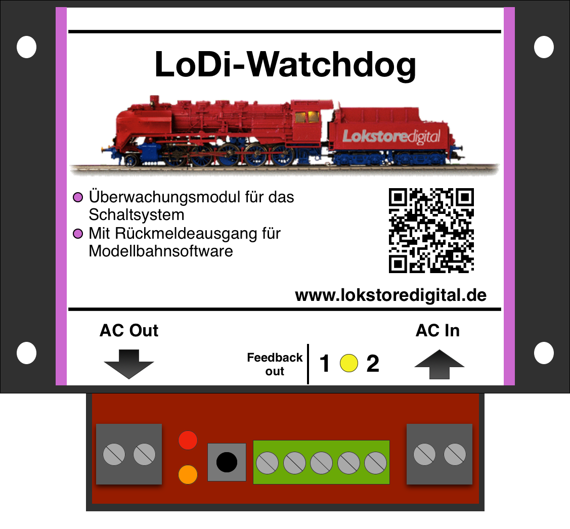
What is the LoDi-Watchdog for?
Customers often tell us that they bridge the limit switches in their solenoid drives, or would like to, for safety's sake. We know the problem all too well, especially on large layouts: up to 70% of the faults behind a turnout that will not throw come down to the limit switches. They are of course a safety feature and protect the drive from being destroyed by too much current or too long a switching time.
But once those limit switches have been removed or bridged and a fault occurs in the system, the LoDi-Watchdog can cut the power straight at the transformer. Every decoder is then dead.
On top of that the LoDi-Watchdog detects every fluctuation on the bus — caused for instance by a faulty network cable or an unterminated bus. A bus that is cut is noticed immediately, and the LoDi-Watchdog can even pass the fault straight on to the model railway software over a feedback channel.
So who exactly needs a LoDi-Watchdog?
Everyone running their layout unattended who wants the greatest possible safety for it together with a simple fault indication — and, as mentioned at the start, everyone who has bridged their limit switches.
What the LoDi-Watchdog does
- It watches the switching system and shuts the transformer system down as soon as it detects a fault.
- Manual operation is possible.
- Switches up to 4 amps.
- With a feedback output for additional monitoring.
1. The LoDi-Watchdog and its connections
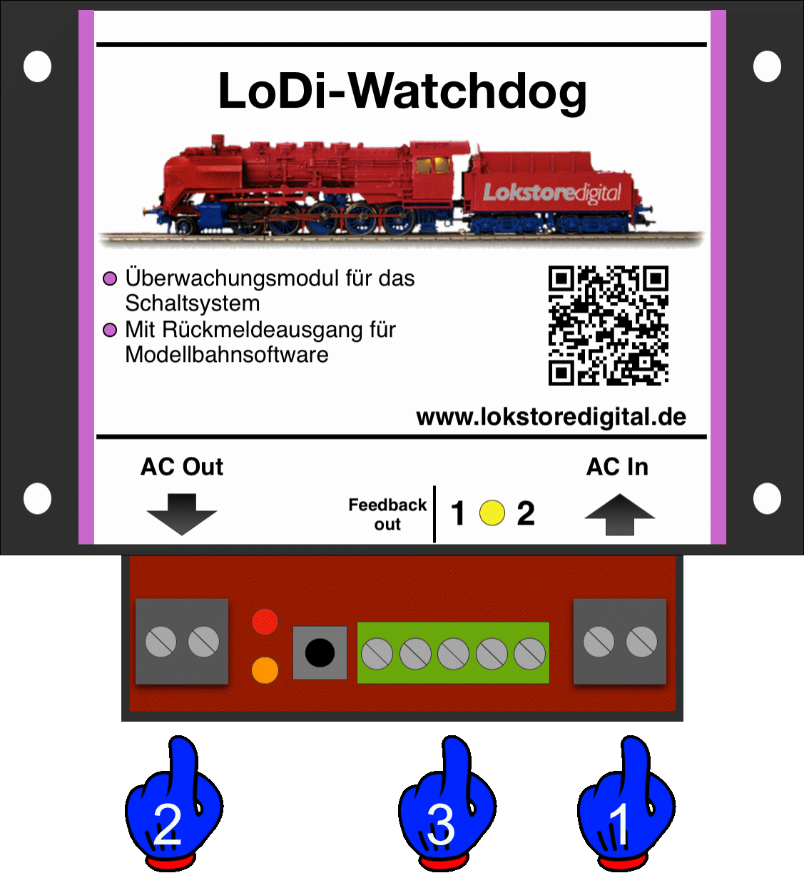
- (1) The transformer or power supply is connected here.
- (2) This is where you connect the LoDi-Operators to be monitored.
- (3) An output of a decoder (LoDi-Operators) is connected to terminal (1 * 2). Two consecutive connections are needed (feedback out). This is where the watchdog can be monitored with a feedback module.
2. LEDs on the LoDi-Watchdog
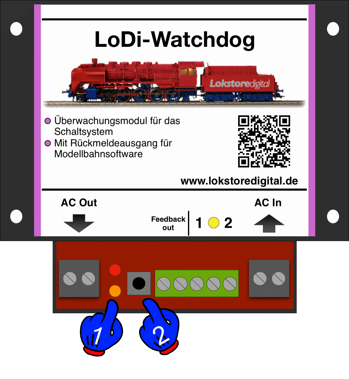
The LoDi-SC-Watchdog has 2 LEDs to help you read the state of the device and understand faults more quickly.
- (1) Orange LED: lights as soon as the LoDi-Watchdog receives power over the AC In terminal. If this LED blinks, there is no voltage at the output terminal.
- (1) Red LED: lights as soon as the LoDi-Watchdog has detected a fault on the bus, or when there is no signal at terminal (1 * 2).
- (2) Button: the LoDi-Watchdog can be operated by hand with this button. You can use it to control the voltage at the AC Out terminal. The LEDs then show: orange steady, red blinking.
3. Connecting to the transformer and the LoDi-Operator
The LoDi-Watchdog is connected to the transformer together with the last LoDi-Operator on the bus. The point is that as soon as the bus fails — because a network cable was pulled, an SC-Booster is not plugged in, or a LoDi-Shift-Commander has stopped working — this is detected and the power is taken off the turnout decoders immediately.
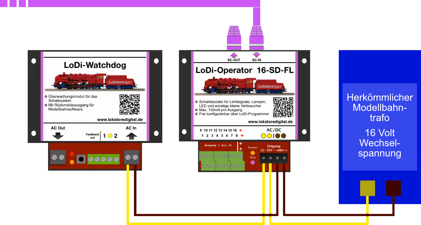
First we connect the transformer to the last device on the bus. That can be any LoDi-Operator (AC, DC or 16-SD-FL).
Then we connect the decoder's supply lead to the watchdog as well, or via the LoDi-Operator as shown in the picture above. Please make sure the lead from the transformer to the LoDi-Watchdog has enough cross-section (0.75 mm² minimum). Ordinary model railway transformers deliver 3 amps and more.

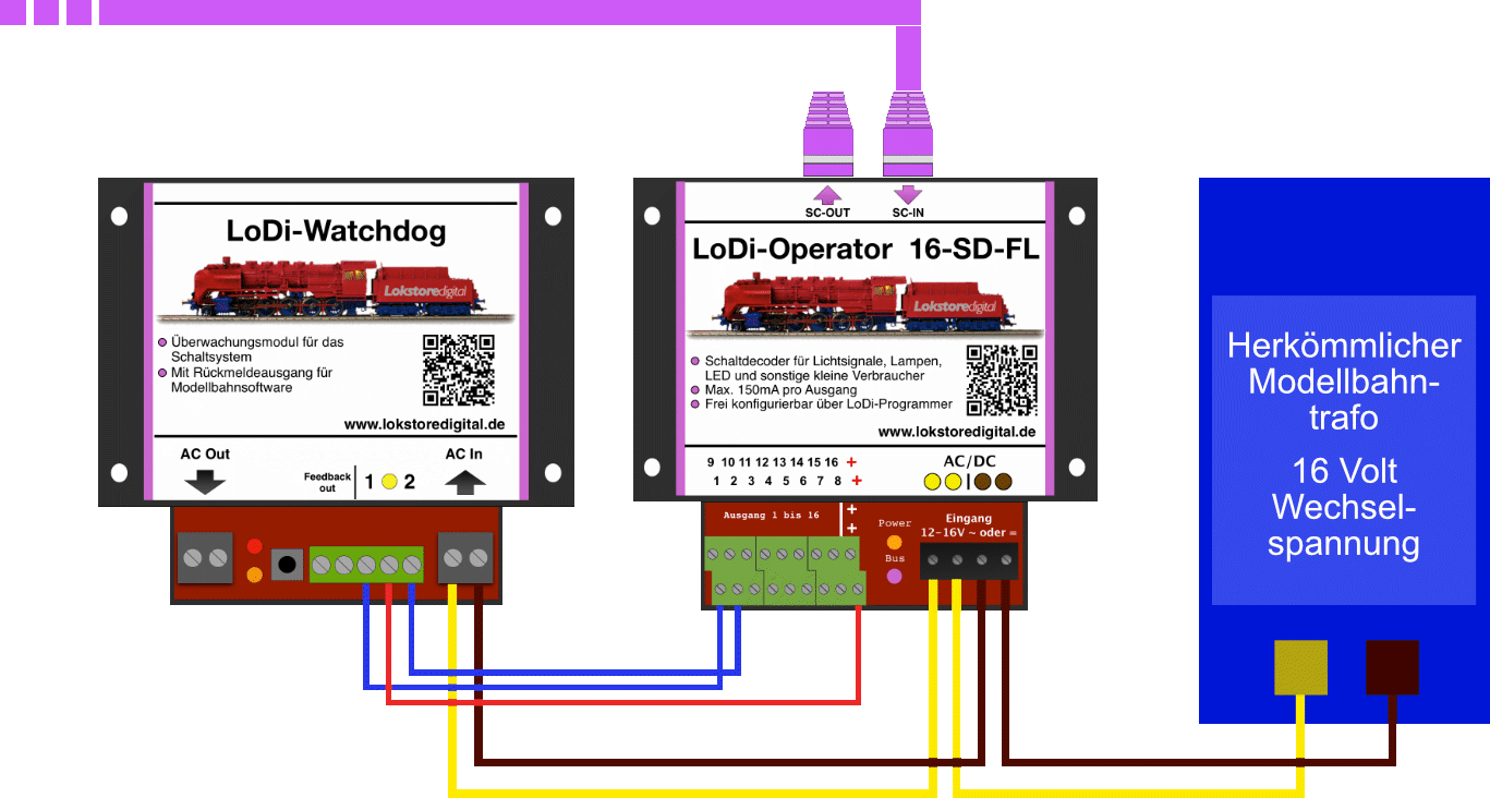
Next the LoDi-Watchdog is connected to the LoDi-Operator 16-SD-FL. Use your usual cable colours for turnouts and accessories; 0.25 mm² is enough here.
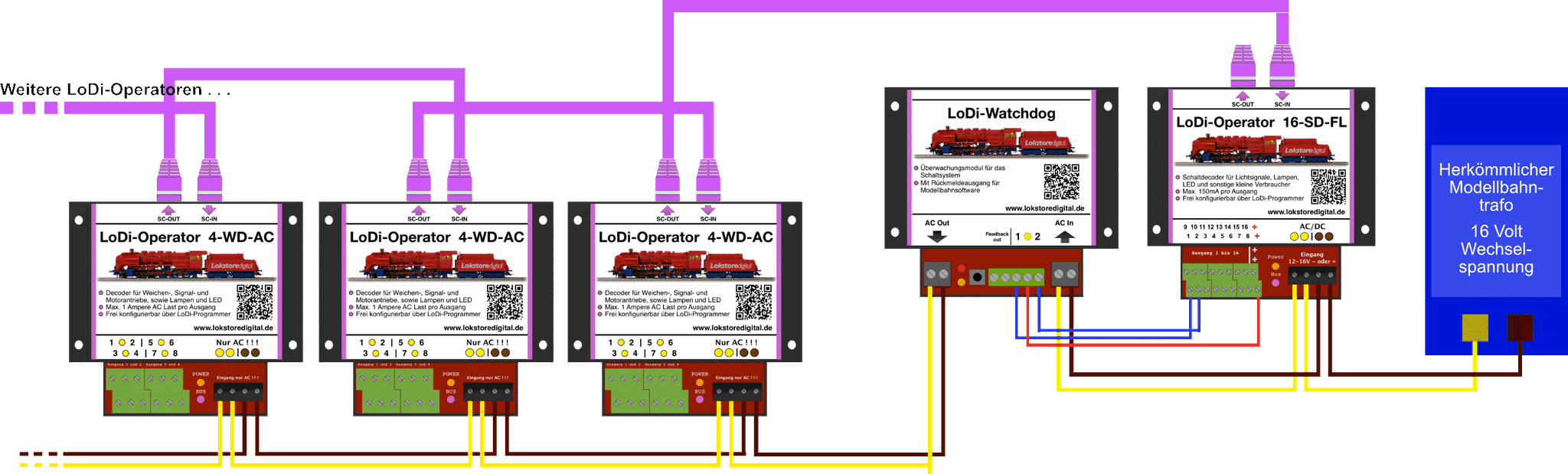
4. Connecting to the turnout decoder system
Now we can connect the LoDi-Operators that supply the turnouts to the AC Out terminal as well. The LoDi-Watchdog delivers 4 amps at most. As a rule turnouts are not all thrown at the same moment, so that is normally enough for a fully populated bus (47 LoDi-Operators 4-WD-AC, for example).
5. Setting the LoDi-Watchdog up in the LoDi-ProgrammerFX
To make the LoDi-Watchdog known to the LoDi-Shift-Commander, navigate in the LoDi-ProgrammerFX to the last module on the bus — in our example that would be a LoDi-Operator 16-SD-FL.
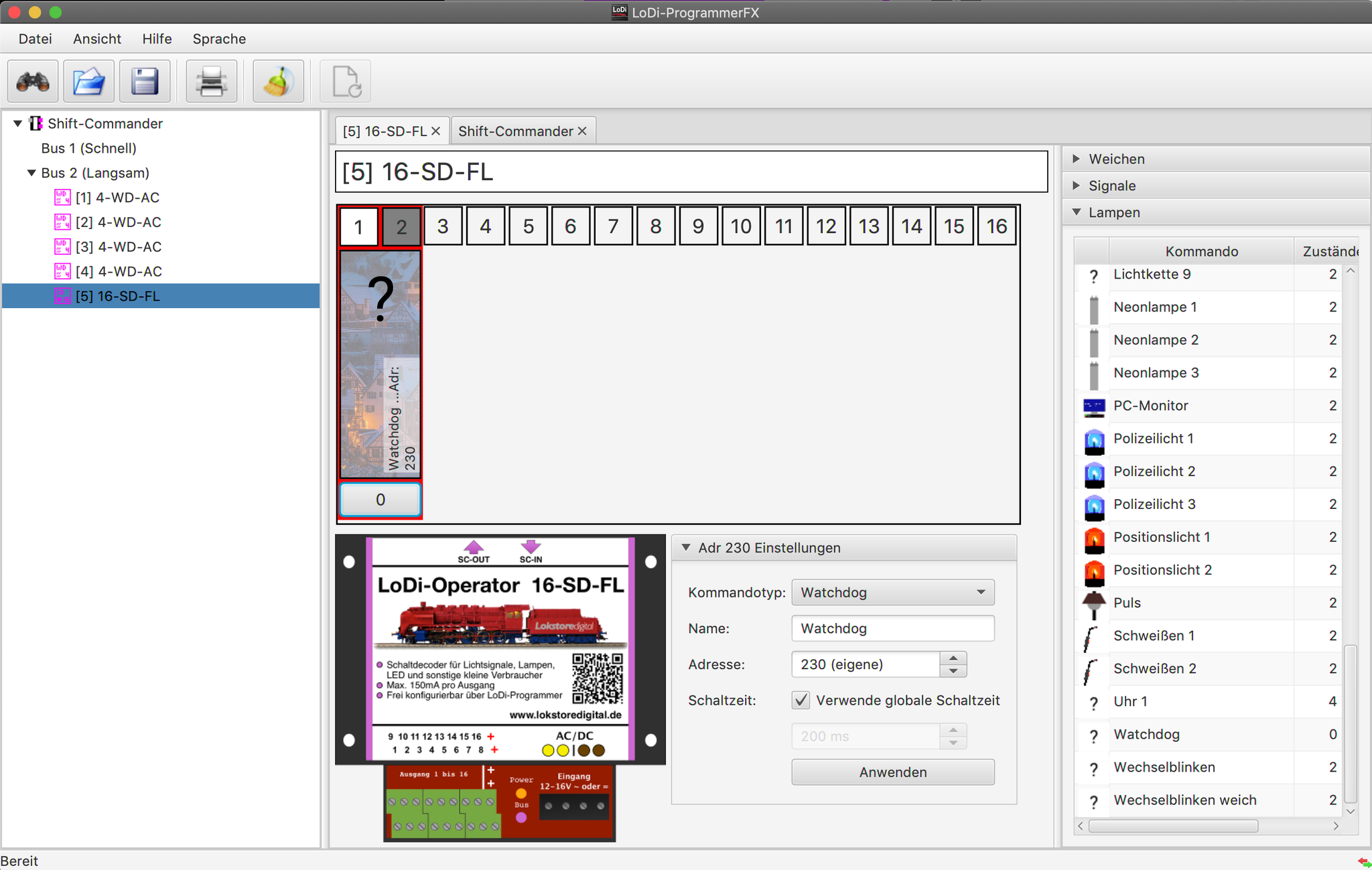
Now click the last operator on the bus. We have connected the LoDi-Watchdog to terminals 1 and 2. In the LoDi-ProgrammerFX you will find the watchdog under "Lamps", at the bottom under "W". Drag it out of the list onto channels 1 and 2.
The LoDi-Watchdog is active straight away. You can also bind the object into your model railway control software. With aspect 1 the LoDi-Watchdog is off, which also switches off the voltage at the AC Out terminal.
6. The LoDi-Watchdog on a feedback module
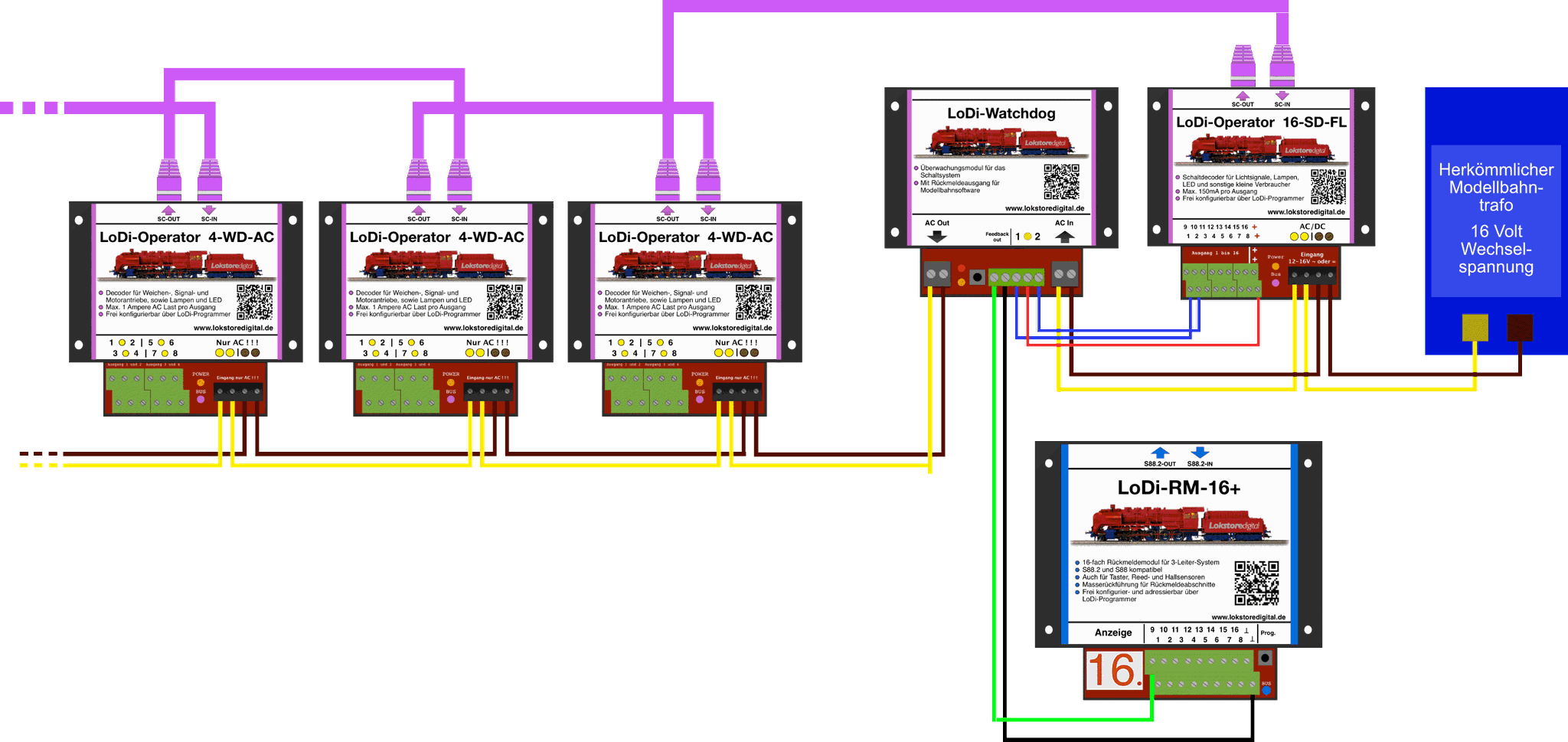
Using the Feedback Out terminal on the LoDi-Watchdog, its state can be monitored from the model railway software through a LoDi-RM-16+ or a LoDi-8-GBM, for example.
5. Download the LoDi-Watchdog as a PDF
Here you can download a summary of the LoDi-Watchdog hardware as a PDF file.

Would you like to see the quality of the devices for yourself?
Get in touch with us HERE!
Visit our forum, where experienced users are happy to help you.