
Software
LoDi-Rektor
Settings and firmware update
The LoDi-Rektor is a powerful command station developed specifically for use with computer-controlled layouts. Its network interface lets it be integrated into existing networks easily, and it can also be controlled conveniently with a Wi-Fi handheld throttle, without model railway software.
The LoDi-Rektor has the LoDi bus (formerly the µCon bus) and can manage up to 62 LoDi bus components on it.
It can generate the following track signals: DCC, mfx® or Motorola.
All devices belonging to the LoDi-Rektor are marked in green. That principle is applied in the device tree as well.
1. The overview
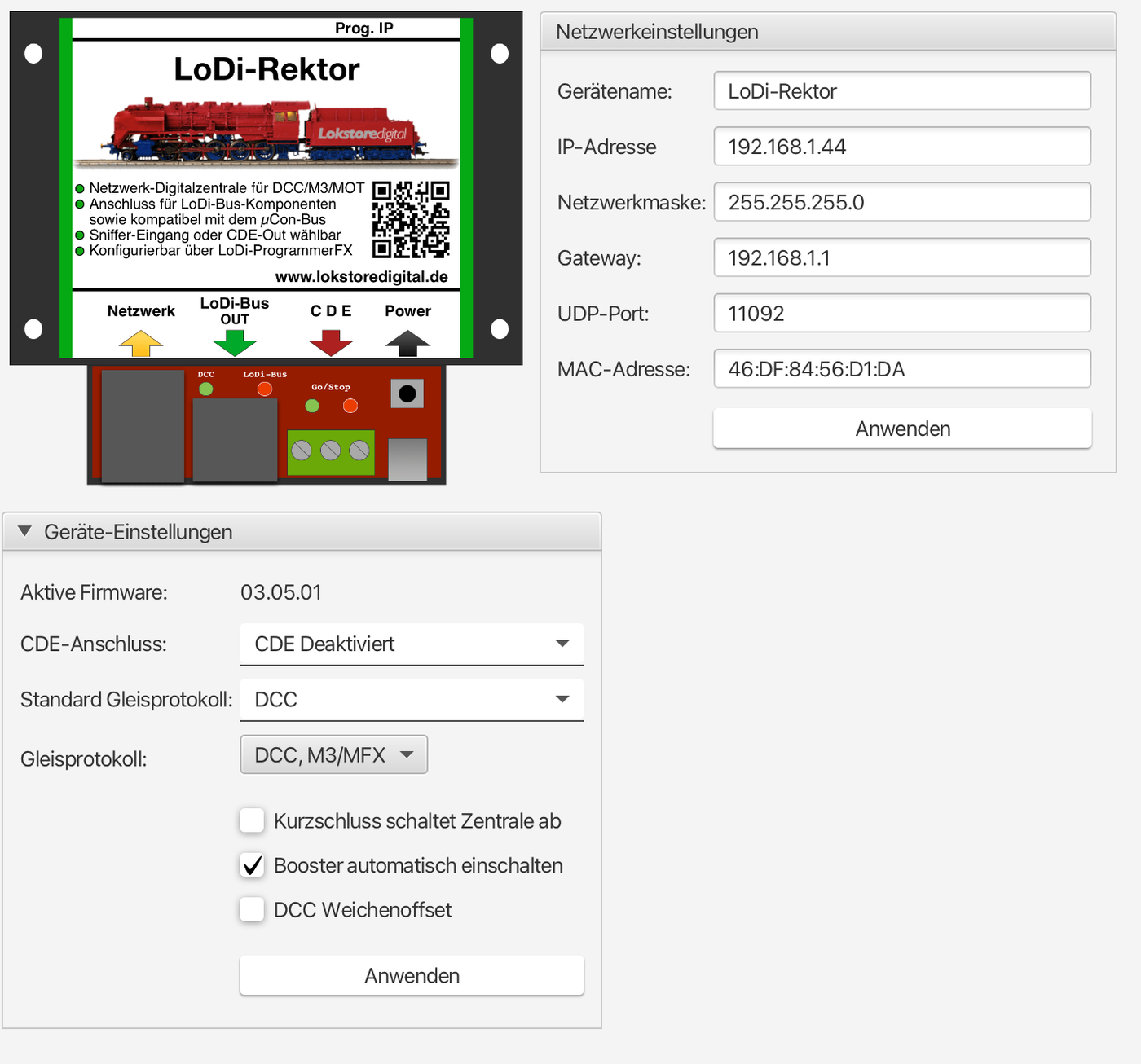
The device editor of the LoDi-Rektor contains the following areas:
- Device settings: determines the behaviour of the CDE connection as well as which track signal is to be generated after starting, and the booster
- Network settings: setting the IP address
- Firmware: updating the LoDi-Rektor's firmware
Network settings
See the network settings in the section Commissioning LoDi devices.
Device settings
- CDE connection: the behaviour of the CDE connection is set here. There are five possible configurations:
- CDE input: the CDE connection is configured as an input. An external command station can be connected to it. The signals generated by that station are passed on to the boosters connected to the µCon bus. Booster faults are reported to the external command station through the connection.
- CDE output: the CDE connection is switched as an output. It puts out the track signals generated by the LoDi-Rektor. Boosters connected to the CDE connection put that signal onto the track. If a booster connected to the CDE connection produces a fault, it is reported to the LoDi-Rektor through the CDE connection.
- CDE output without E: treated like the CDE output, but E is not evaluated.
- CDE sniffer: CDE is set to input, the Rektor remains the command station, but in this configuration a DCC command station can be connected and kept in use for controlling.
- CDE disabled: the CDE connection is off. It neither generates booster signals nor responds to signals from other command stations or boosters.
2. The device tree
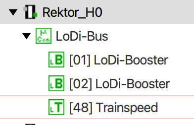
The LoDi-Rektor is shown in the device tree as follows:
- LoDi-Rektor: this is where the LoDi-Rektor's device and network settings live
- LoDi bus: the LoDi bus serves the LoDi bus devices connected to it.
- LoDi bus devices: below the µCon bus, the LoDi bus devices found are shown in address order. Boosters newly plugged into the bus are detected and shown automatically.
- CDE: this node is only shown if the CDE connection has been configured as "output". It is shown as a booster below the µCon bus and reflects the status of the boosters connected to the CDE connection.
To open the settings for a device or bus, it is enough to click the corresponding entry in the device tree. The corresponding dialogue opens in the main area.
To get an overview of which device is behind which entry, you can hold the mouse over the entry in the device tree for a few seconds. The device is then shown with its picture as a tooltip.
3. Driving, switching, CV programming
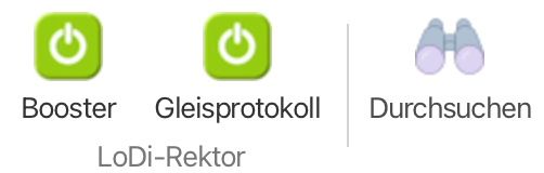
To be able to drive a locomotive or switch a turnout over DCC or Motorola, the booster voltage as well as the track signal first have to be switched on. With the LoDi-Rektor selected in the menu on the left, two entries appear at the far left of the menu bar at the top: booster voltage and track protocol. Both have to be green to put voltage onto the track.
Driving

In the menu bar you will find the entry "Steuern". When you click that entry, a dialogue with a selection opens. Depending on how many LoDi devices you have on your network, the control in question is offered to you here.
In this case we want to drive first. So click "Fahren" and then the command station, in this case the LoDi-Rektor.
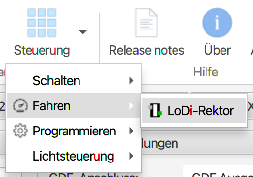
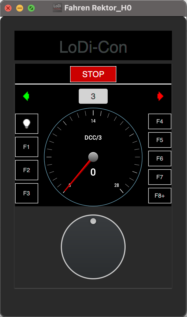
Once you have clicked the LoDi-Rektor, the throttle opens, modelled on the LoDi-Con. There you can now enter the locomotive number and call up the locomotive and its functions.
The throttle is detached from the LoDi-ProgrammerFX. That means you can place it freely on the screen, or even on another screen. Beyond that it is also possible to open further throttles, in order to control several locomotives at once, for instance.
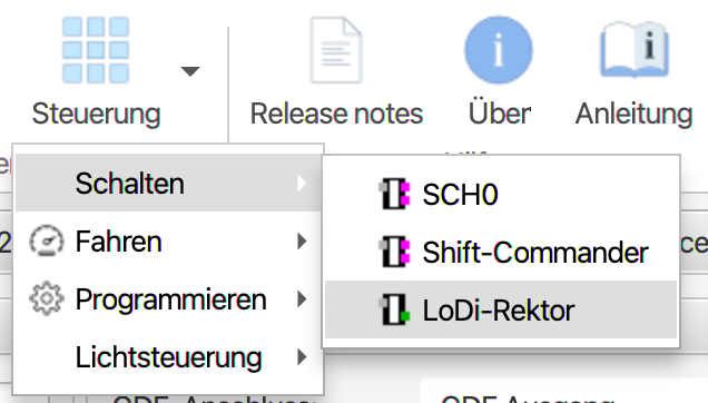
Switching. To switch a turnout over DCC, Motorola or the LoDi-Shift-Commander, click "Steuerung" at the top of the dialogue again. Then select "Schalten". If any are present, you will now see all the command stations that can switch listed.
In our case we want to switch accessories over DCC or Motorola with the help of the LoDi-Rektor. So now click the LoDi-Rektor.
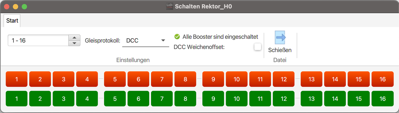
A further window now opens in which the turnouts can be switched. Sixteen turnouts can be driven at once. The 1–16 selection lets you move on to the next pairs of addresses.
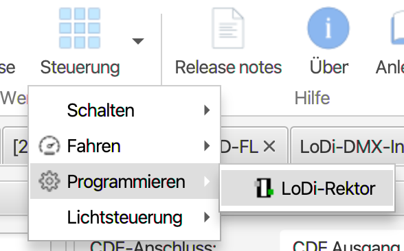
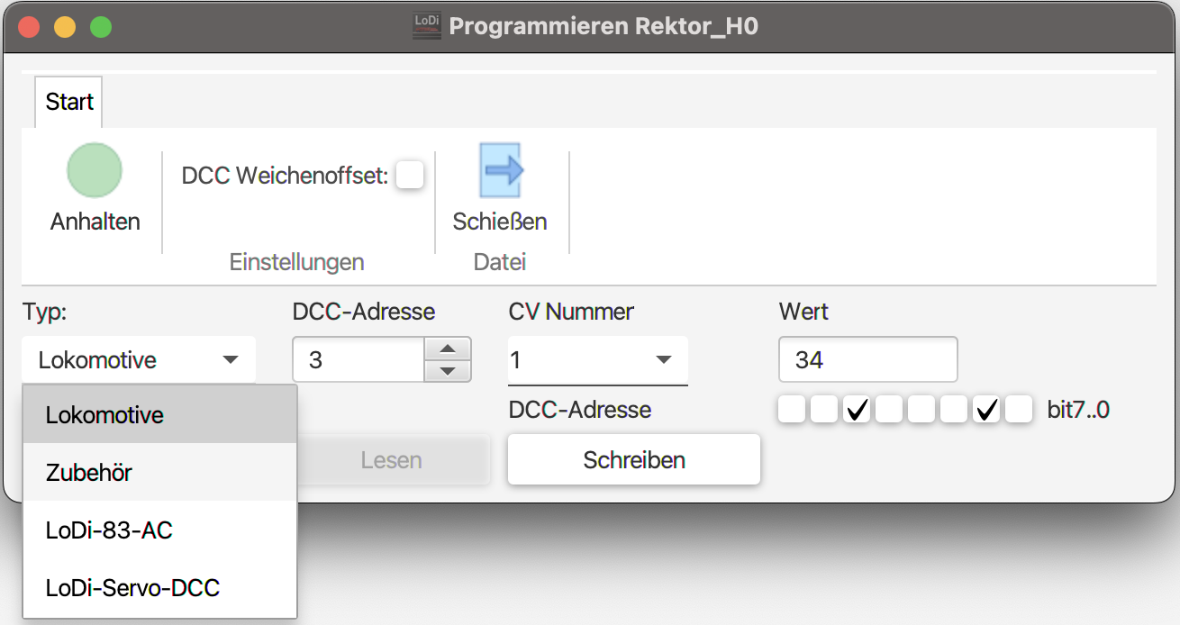
CV programming. The CVs of locomotives and of accessory decoders can be configured through the LoDi-Rektor. The LoDi-Rektor does not have a programming track, but it can set the decoders' CVs over PoM (programming on main). Click "Steuerung" again, then go to "Programmieren" and select the LoDi-Rektor here again. The programming dialogue opens, in which you can now change the CVs for locomotives and accessories.
If you have a LoDi-CV-Programmer, you can also read the CVs of locomotives or accessory decoders. The locomotive decoder, the locomotive or the accessory decoder has to be connected to the programming track for that.
4. The LoDi bus overview
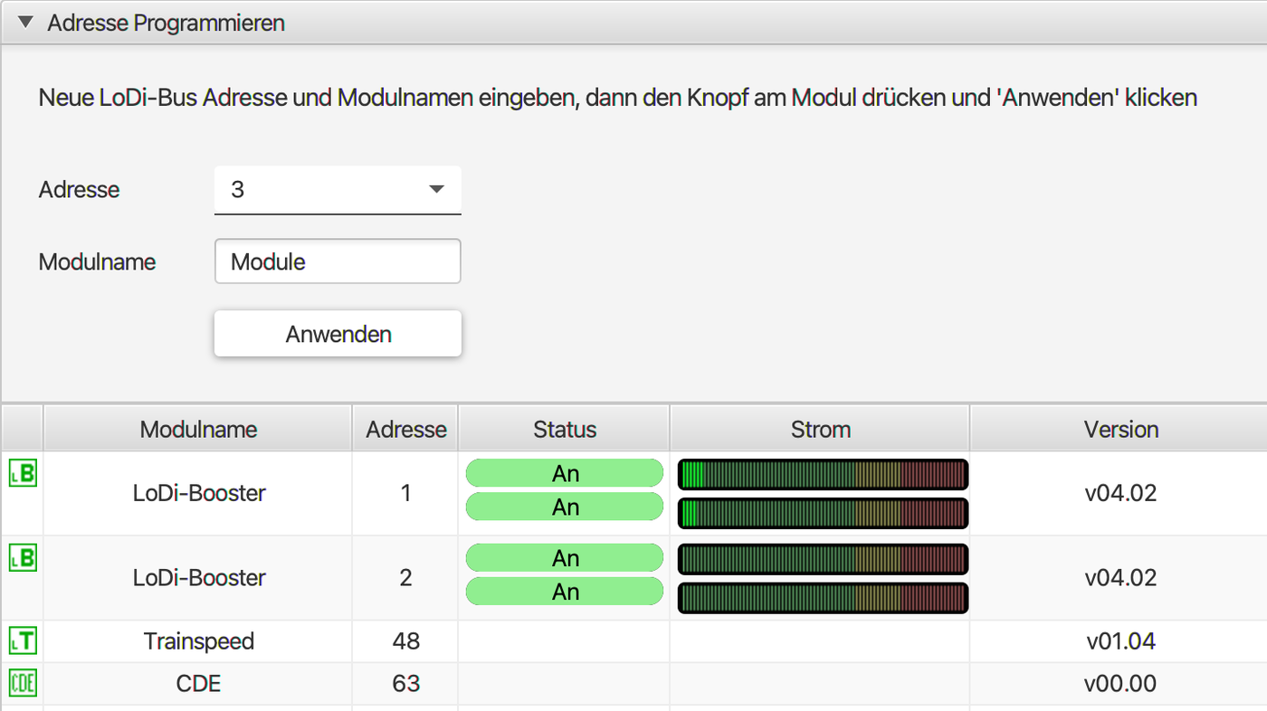
The LoDi bus dialogue shows all the devices connected to the LoDi bus. It is divided into two areas:
- The upper area serves to programme the booster address and the booster name.
- In the lower area the modules found on the µCon bus are shown in a table.
- LoDi module name: the name assigned to the µCon device
- LoDi address: the µCon device's current address
- Status: shows a booster's current status. It can also be switched at this point. The following states are possible:
- On: the booster channel is switched on
- Off: the booster channel is switched off
- Short circuit: the booster channel reports a short circuit
The LoDi bus dialogue lets you change the LoDi addresses of the connected devices. Proceed as follows:
- Enter a LoDi address and a LoDi module name. The module name may be 16 characters long.
- Press the "Prog." button on the LoDi bus component to be programmed. In the table below, the corresponding booster is highlighted in red.
- Now press the "Anwenden" button.
A precise description of how to configure the LoDi-Booster or LoDi-TrainSpeed and assign an address can be found here: LoDi-Booster, LoDi-Booster 10A and LoDi-TrainSpeed software descriptions.
5. The CDE connection
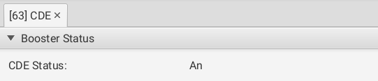
The CDE node is only shown if the CDE connection has been configured as "CDE output" or "CDE output without E".
It shows the status of the boosters connected to the CDE connection.
7. Firmware update
From the LoDi-ProgrammerFX 2025.01 onwards there is an online updater for the devices' firmware. We show you here how to install firmware.
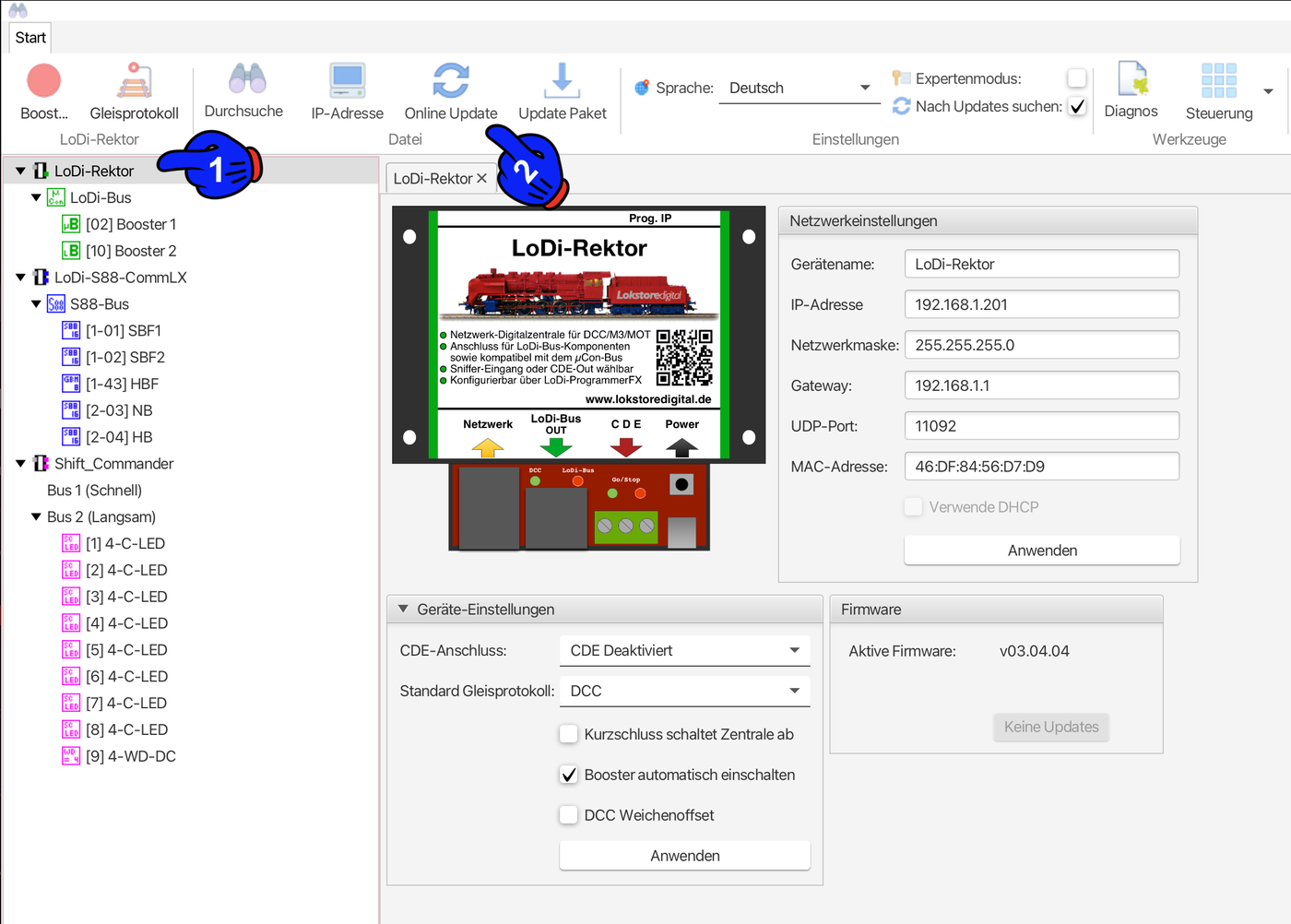
First click the device that is to be updated, in this case the LoDi-Rektor (1). A new menu item now appears in the bar at the top: "Online-Update".
The update dialogue opens and the server automatically searches for available updates.
Then select the newest version shown (3) and click Install update (4). In the next dialogue the currently installed version and the version to be installed are shown to you once more.
Confirm the process by clicking OK to start the update. Once the update is finished, the device restarts automatically. If the current version is already installed, the LoDi-ProgrammerFX will say so.
8. The Z21 compatibility mode
From version 3.0.1 onwards, the LoDi-Rektor offers the option of connecting a Roco® Wi-Fi handheld throttle directly or through the Z21 app.
To do that you have to enter the LoDi-Rektor's IP address as the target or host address.
Beyond that, the LoDi-Rektor can now be used with model railway control software such as TrainController®, Railcontrol or others that support the Z21 protocol. Please note here that boosters cannot currently be controlled individually over the Z21 protocol; the complete system can only be switched on and off with start/stop.

Any questions still open?
Would you simply like to ask us in person?
Or go to our forum, where experienced users are glad to help you further.
In this section
- LoDi-Booster
The [LoDi-Booster](docs:lodi-booster) converts the control signal coming from the command station over the LoDi bus into the track voltage. The LoDi-Booster has the following features:
- LoDi-Booster 10A (+)
The [LoDi-Booster 10A](docs:lodi-booster-10a) and the [LoDi-Booster 10A+](docs:lodi-booster-10a-plus) convert the control signal coming from the command station over the LoDi bus into the track voltage. The LoDi-Booster has the following features:
- LoDi-CV-Programmer
Like the LoDi-Booster, for instance, the LoDi-CV-Programmer converts the control signal coming from the LoDi-Rektor over the LoDi bus.
- LoDi-TrainSpeed
Like the LoDi-Booster, the LoDi-TrainSpeed converts the control signal coming from the LoDi-Rektor over the LoDi bus.