
Software
LoDi-Booster
Settings and firmware update
The LoDi-Booster converts the control signal coming from the command station over the LoDi bus into the track voltage. The LoDi-Booster has the following features:
- two separately switchable booster channels
- adjustable sensitivity for short circuits
- RailCom support (generating the RailCom cutout)
- built-in current, voltage and temperature measurement
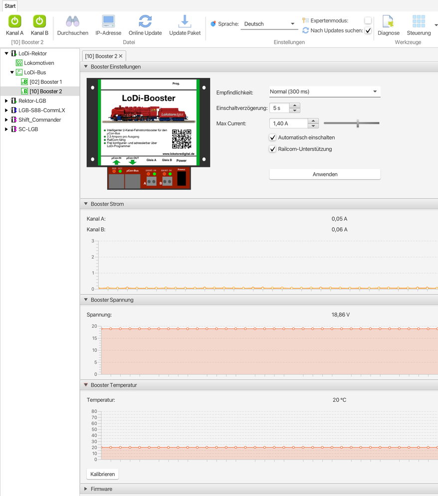
The LoDi-Booster dialogue tries to present all these properties clearly. All areas can be folded open and closed. That way only what is really needed at the moment is shown.
The dialogue is divided up as follows:
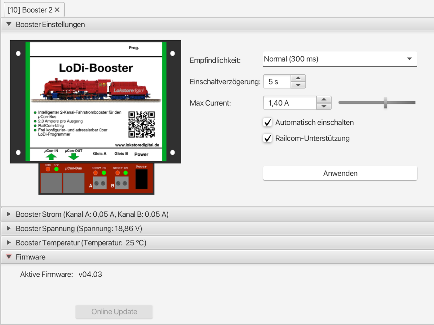
- Booster settings: sets the settings stored in the LoDi-Booster.
- Booster status: shows the current booster status and allows the booster channels to be switched on and off.
- Booster current: measures the current draw on both booster channels.
- Booster voltage: measures the track voltage of both booster channels.
- Booster temperature: shows the temperature inside the device.
1. Changing the LoDi-Booster's µCon bus address
As delivered, the LoDi-Booster is set to address 1, as mentioned above. That can stay as it is and only has to be changed if you want to add another LoDi-Booster to the system.
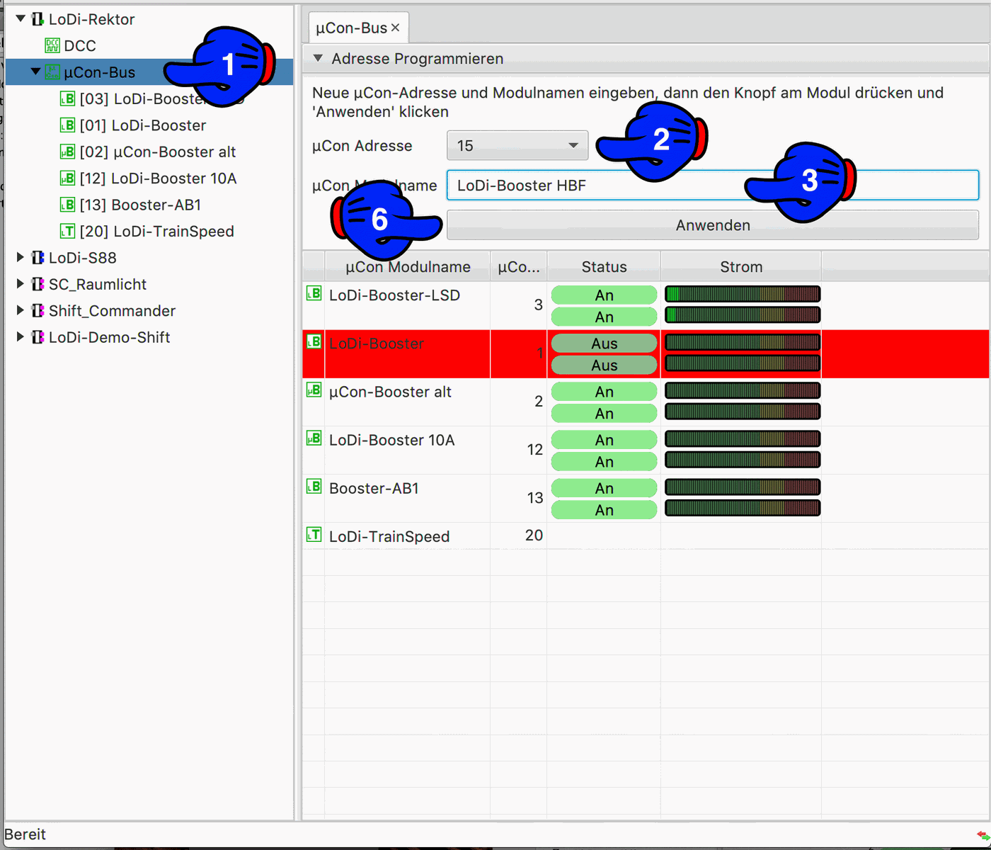
Now select the new address the device is to be given (2). A name for the device can then also be entered at (3).
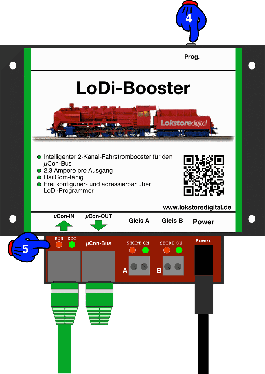
Now press the Prog. button (4) on the LoDi-Booster for 3 seconds. The LoDi-Booster now jumps into addressing mode. It signals this through the two LEDs (5), which flash alternately.
Now the "Anwenden" button (6) in the LoDi-ProgrammerFX can be pressed. The TrainSpeed stops flashing immediately and has its new address set from now on.
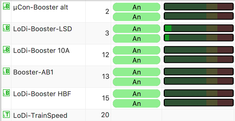
The LoDi-Booster has now saved the new address and is shown on the bus again straight away.
2. The LoDi-Booster's settings
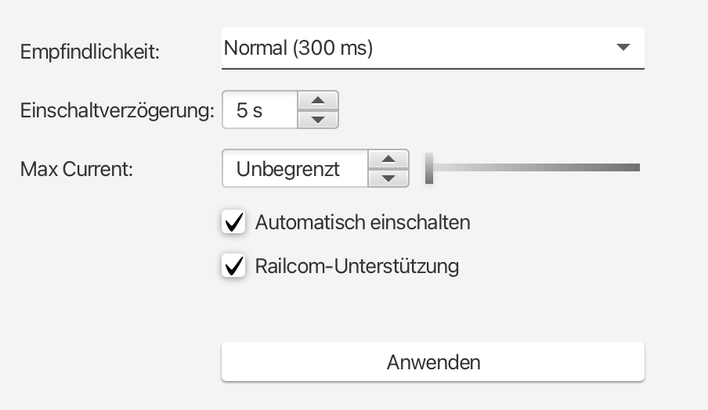
The LoDi-Booster stores its settings in internal memory.
All settings are applied and stored in the booster by pressing the "Anwenden" button.
This dialogue offers the following settings:
- Sensitivity: sets the time after which, once the short-circuit threshold is exceeded, a short circuit is detected. The actual sensitivity also depends on how often the short circuit occurs. Three-rail operators should set a higher threshold here to avoid problems when running over turnouts.
- very fast: 100 ms
- fast: 200 ms
- normal: 300 ms
- slow: 400 ms
- very slow: 500 ms
- Individual short-circuit times up to 2500 ms can also be entered in the sensitivity field. That is possible on the LoDi-Booster from firmware version 2.03 onwards.
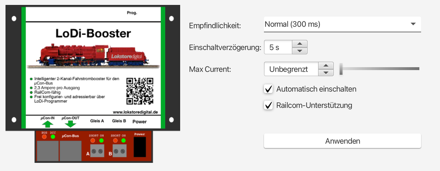
- Switch-on delay: the switch-on delay gives the waiting time before the track voltage is switched back on after a short circuit.
- Max current: here the maximum current limit can be set with a slider in 100 mA steps. (From FW V4.03.)
- Switch on automatically: if this option is set, the booster automatically switches the track voltage back on after a short circuit, observing the waiting time defined in "switch-on delay". If this option is not set, the booster has to be switched back on manually, either from the software or by pressing the button on the booster.
- RailCom support: if this option is set, the booster generates a RailCom cutout after every DCC packet. That is necessary in order to receive the data sent by the decoders in the LoDi-8-GBM feedback modules. Only set this option if you are using DCC or mfx® with RailCom.
3. Status and displays
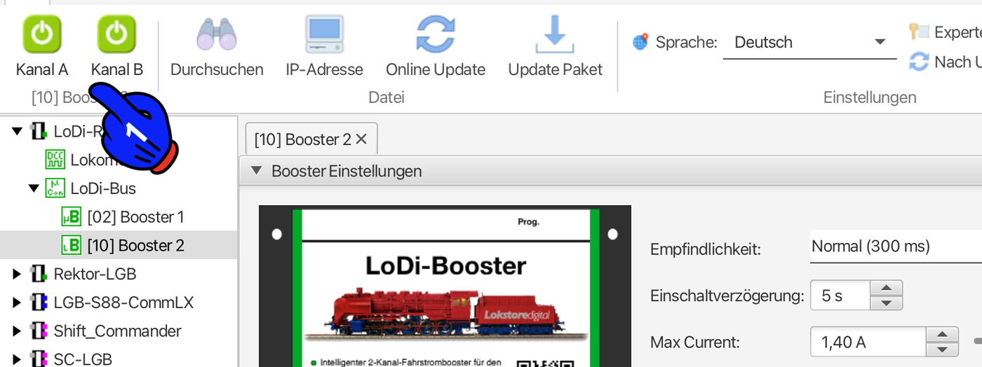
From LoDi-ProgrammerFX version 5.2025 onwards, the boosters' status is shown directly in the status bar at the top. That does away with folding further tabs open, and the current status of active boosters is immediately visible.
- On: the channel is switched on. If a track signal is present, the track voltage is switched through.
- Off: the channel is switched off. No track voltage is present.
- Short circuit: the channel reports a short circuit. The track voltage is switched off in this state.
In further fields, which can be folded open or closed at the bottom of the LoDi-ProgrammerFX, the booster can show current, voltage and, from firmware version 2.00 onwards, the device's temperature.
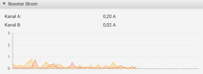
This area shows the current draw of the two booster channels over time.
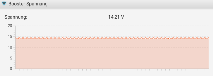
This area shows the voltage of the two booster channels over time.
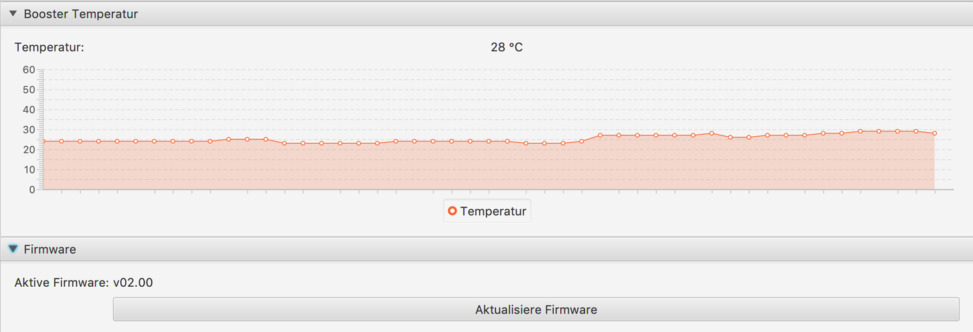
This area shows the temperature of the booster over time, measured near the output stage. If the value rises, the fan output adapts.
4. Updating the LoDi-Booster's firmware
The LoDi-Booster can be updated through the LoDi-Rektor.
From the LoDi-ProgrammerFX 2025.01 onwards there is an online updater for the devices' firmware. We show you here how to install firmware.
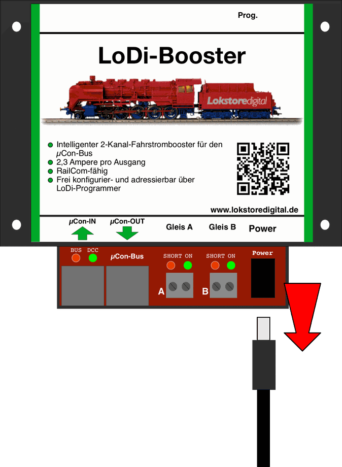
To upgrade the firmware on the LoDi-Booster, you first have to put the device into bootloader mode.
To do that, first pull the power cable out of the LoDi-Booster.
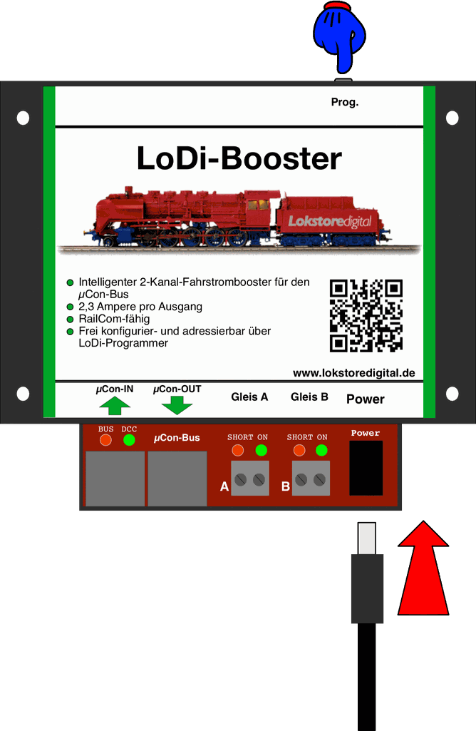
To activate the bootloader in the LoDi-Booster, you have to hold the Prog. button at the back of the booster down and plug the power connector back into the LoDi-Booster at the same time.
Once the power cable is plugged in you can let go of the button.
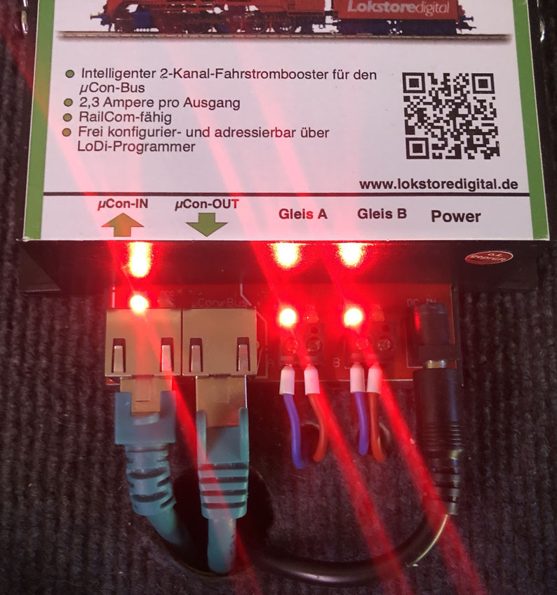
The LoDi-Booster is now in bootloader mode. It signals this by all the LEDs on the device glowing red.
Only the LED at the µCon bus works as usual and signals an active bus by flickering.
(Only if the LoDi-Rektor is connected and active.)
The booster is now shown in the LoDi-ProgrammerFX, but all the displays are now greyed out; that is how the LoDi-ProgrammerFX signals that the LoDi-Booster is in bootloader mode.
Apart from the firmware update, nothing further is possible now.
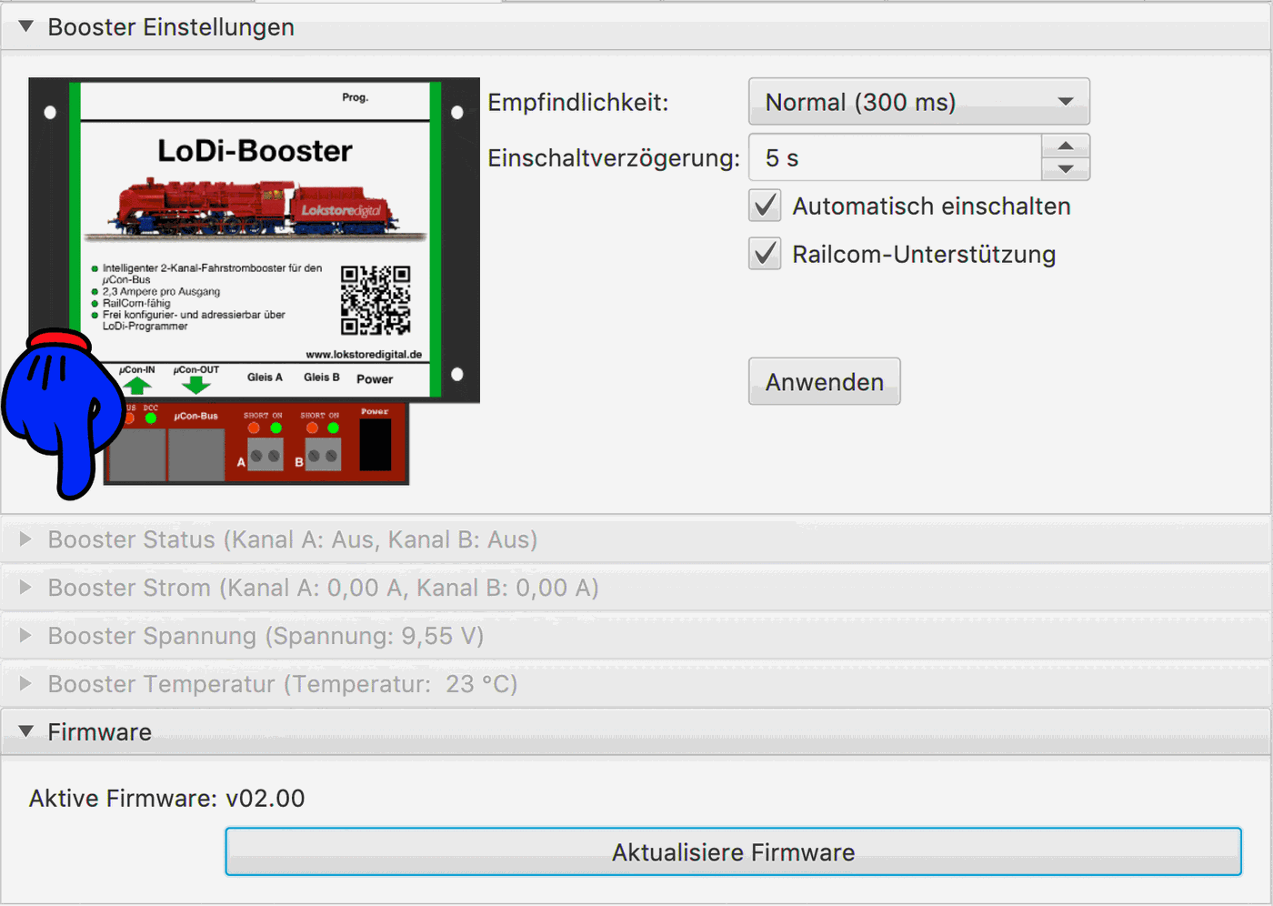
As mentioned already, the LoDi-ProgrammerFX has offered an online update function since version 2025.01. It lets the devices' current versions be shown right in the dialogue and installed immediately.
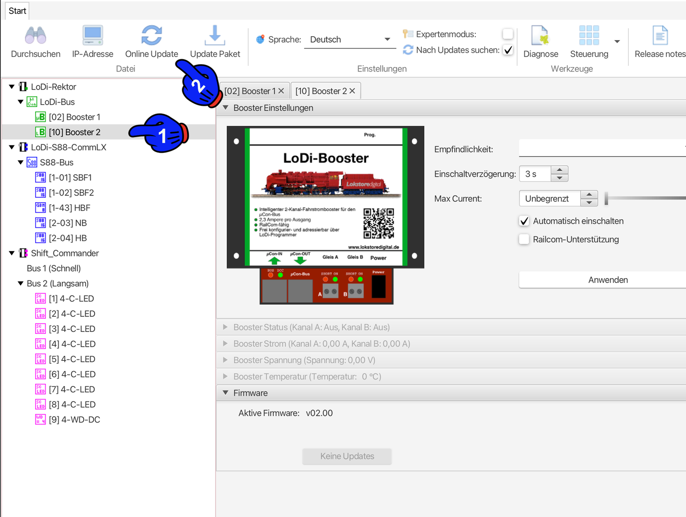
Now click the LoDi-Booster that is in the bootloader. A new menu item now appears in the bar at the top: "Online-Update".
The update dialogue opens and the server automatically searches for available updates.
Then select the newest version shown (3) and click Install update (4). In the next dialogue the currently installed version and the version to be installed are shown to you once more.
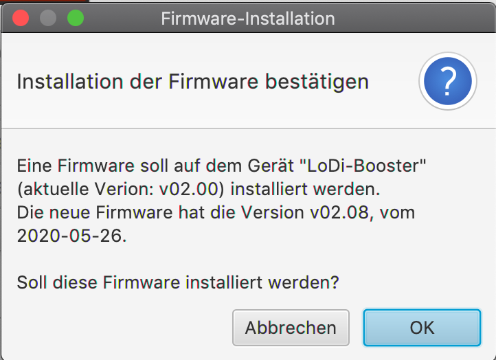
Now you still have to confirm the update.
After pressing the OK button, a progress bar now runs at the bottom right of the LoDi-ProgrammerFX.

The LoDi-Booster reboots once after the update and then reports back on the LoDi bus as usual straight away. A quick check shows that the current firmware is now installed. Should it keep flashing red after the update, disconnect the booster from the power briefly and plug it back in.
5. Connecting and setting up the LoDi-Booster
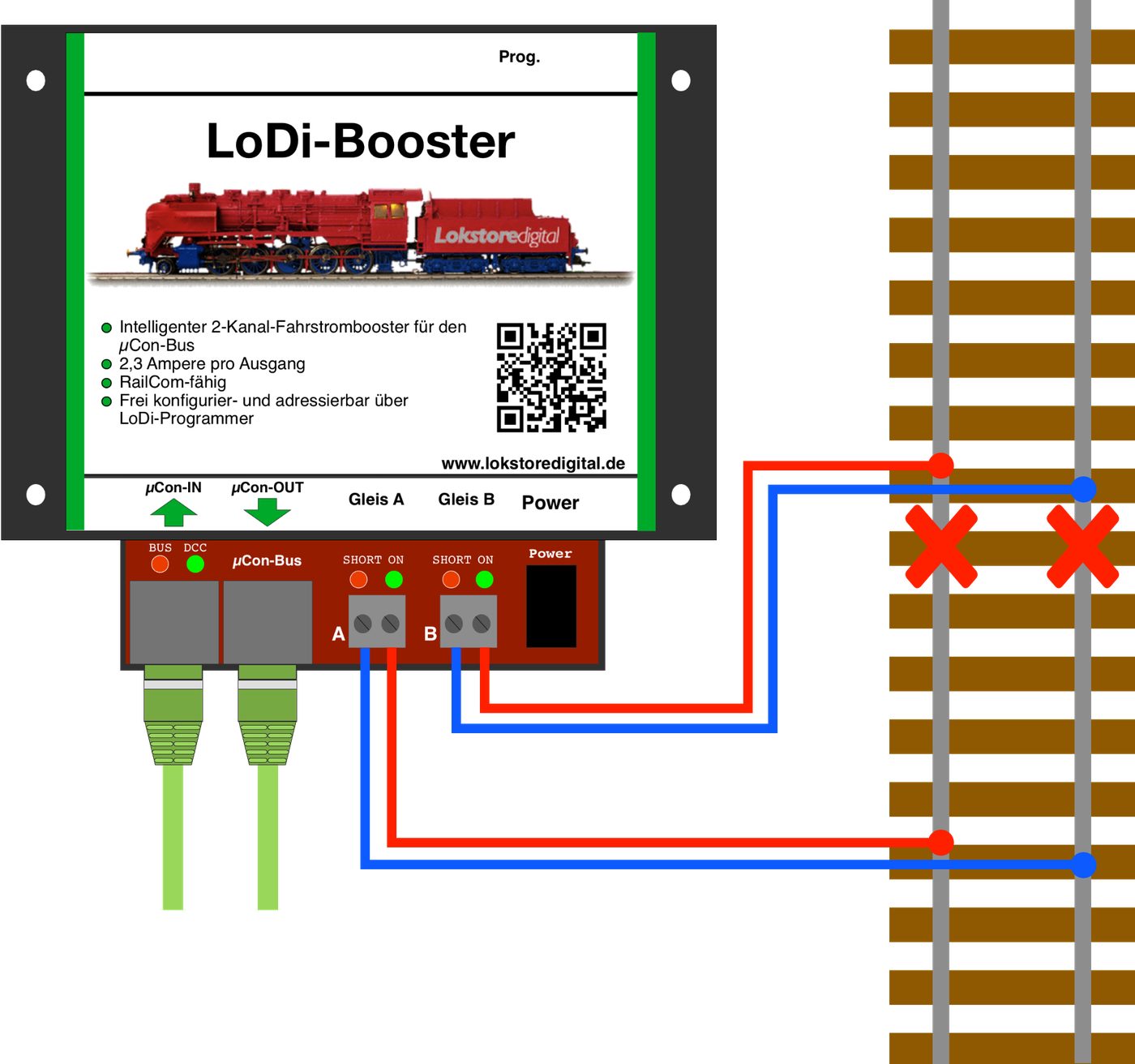
Click here to reach the LoDi-Booster hardware description.

Any questions still open?
Would you simply like to ask us in person?
Or go to our forum, where experienced users are glad to help you further.