
Software
LoDi-Shift-Commander
Settings and firmware update
The LoDi-Shift-Commander is the interface between all the LoDi operators and the model railway software. Like the LoDi-Rektor or the LoDi-S88-Commander LX, it was developed for the highest efficiency in use.
There are 2 buses on the LoDi-Shift-Commander: the first bus is the "fast" one and the second the "slow" one. A total of up to 60 LoDi operators can be connected to the LoDi-Shift-Commander.
All devices belonging to the LoDi-Shift-Commander are marked in purple. That principle is applied in the device tree as well.
1. The overview
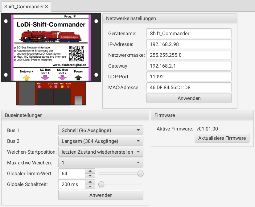
The device editor of the LoDi-Shift-Commander contains the following areas:
- Bus settings: setting the LoDi-Shift-Commander's two SC buses
- Network settings: setting the IP address
- Firmware: updating the LoDi-Shift-Commander's firmware
- Bus 1 and bus 2: the two SC buses can be run either as a light bus (fast) or as a switching bus (slow). Bus 1 can only be used as a light bus, bus 2 as both a light and a switching bus. Depending on the setting, not only the number of outputs changes but other properties as well:
- Fast (96 outputs): this setting is used mainly for light signals and lighting effects. Each output can be dimmed in 64 steps between off and on. The repeat rate is 100 Hz. We recommend connecting LoDi-Operator 16-SD-FL modules to this bus.
- Slow (384 outputs): this setting is used for switching outputs such as turnouts or mechanical signals. All LoDi controller modules, such as the LoDi-Light-Operator 4-C-LED, can only be run on the light bus.
- Turnout starting position: sets how the turnouts are initialised when the LoDi-Shift-Commander starts.
- No initialisation: the turnouts are not driven. That makes sense if the model railway control software switches the turnouts into the right position itself at startup.
- Restore the last state: the turnouts are brought into the position last switched.
- Run through all positions once: every possible state is reached once for every turnout. After that the last known state is restored. That is useful above all for motor turnout drives which can only travel in one direction from the mid position.
The "Anwenden" button applies all the settings and writes them to the device. The device then restarts automatically.
Network settings
See the network settings in the section Commissioning LoDi devices.
2. The bus overview and assignment
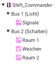
The LoDi-Shift-Commander is a layout's switching centre. It controls turnouts, signals, lighting effects and the room lighting.
All devices belonging to the LoDi-Shift-Commander are marked in violet. That principle is applied in the device tree as well.
The LoDi-Shift-Commander is shown in the device tree as follows:
- LoDi-Shift-Commander: this is where the LoDi-Shift-Commander's device and network settings live
- Bus 1: this bus is always run as a light bus. It has 96 outputs in total and suits light signals and lighting effects. If too many modules are connected, the surplus modules on the bus are not detected.
- Bus 2: depending on the device setting, this bus is run in two different modes:
- Light bus: 96 dimmable outputs
- Switching bus: 384 non-dimmable outputs
- Normal operator modules: map the outputs directly and are configured uniformly. Example: the LoDi-Operator 16-SD-FL
- Controller modules: provide special functions and, depending on the type, have a dedicated setup interface. These modules can only be run on the switching bus (bus 2 as a switching bus). Example: the LoDi-Light-Operator 4-C-LED (room lighting control)
To open the settings for a device, bus 1 or bus 2, it is enough to click the corresponding entry in the device tree. The corresponding dialogue opens in the main area.
To get an overview of which device is behind which entry, you can hold the mouse over the entry in the device tree for a few seconds. The device is then shown with its picture as a tooltip.
Bus 1 and bus 2
The bus 1 and bus 2 nodes represent the LoDi-Shift-Commander's two SC bus connections. Below the bus nodes, the devices are shown in the order in which they were found starting from the SC bus connection.
When reading the modules in, it is checked whether the number or the kind of modules has changed. If a deviation from the last stored bus configuration is found, both buses are switched off. The bus with the deviating bus configuration is highlighted in red. On the LoDi-Shift-Commander the bus LEDs flash.
This functionality makes sure the signals come out at the right output when work is done on the bus. It is therefore to be understood as a protective measure.
To put the bus back into service, you have to click the corresponding bus node and assign the modules correctly in the bus dialogue that appears.
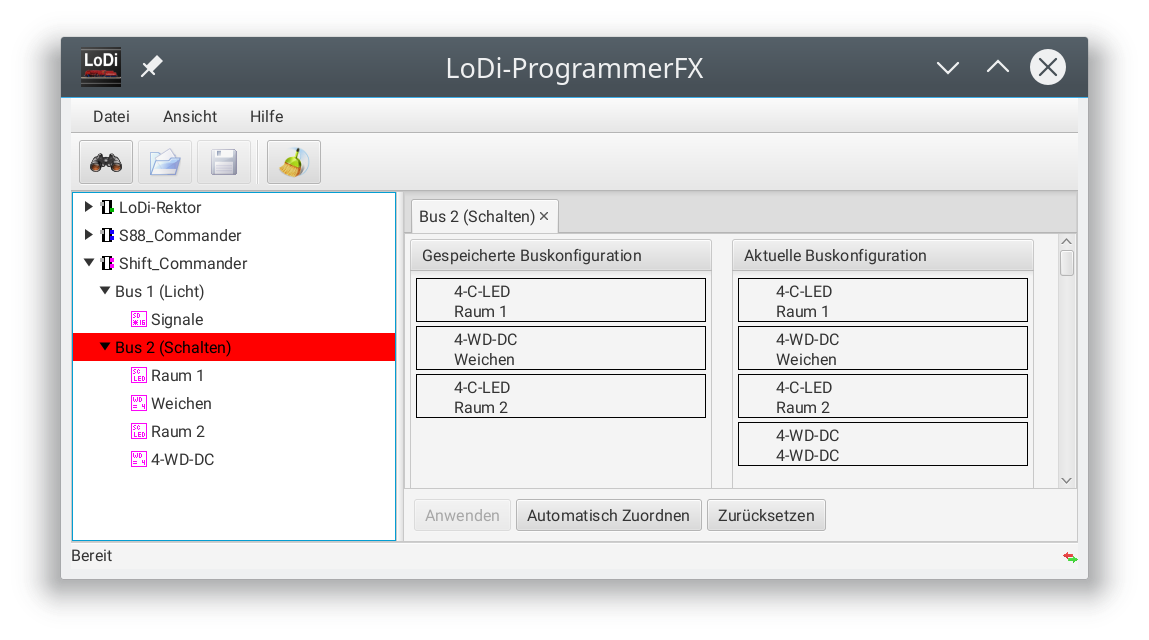
In the screenshot above, a module has been added to the bus. In that case it is enough to press the "Automatisch Zuordnen" button.
If the automatic assignment does not do the job, remaining modules can be assigned by hand with drag and drop or through the context menu.
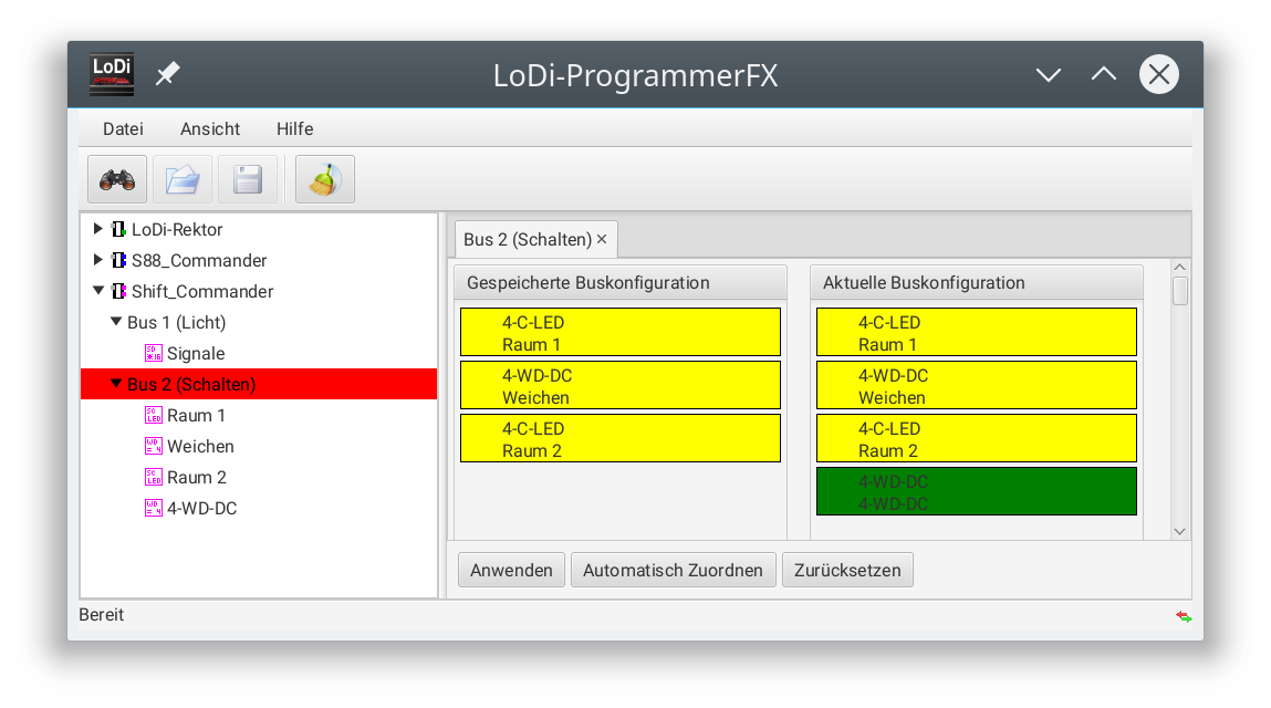
The colour coding of the modules is as follows:
- Yellow: the module stays on the bus.
- Green: the module has been added.
- Red: the module has been removed from the bus.
To find out how the modules have been assigned, you can hold the mouse over a module. Its counterpart is then highlighted.
The "Zurücksetzen" button undoes all the assignments made previously.
When the "Anwenden" button becomes active, the new bus configuration can be applied. When applying it, the commands on the modules are moved or removed with the modules. Once it has been applied successfully, both buses are active again.
3. Firmware update
From the LoDi-ProgrammerFX 2025.01 onwards there is an online updater for the devices' firmware. We show you here how to install firmware.
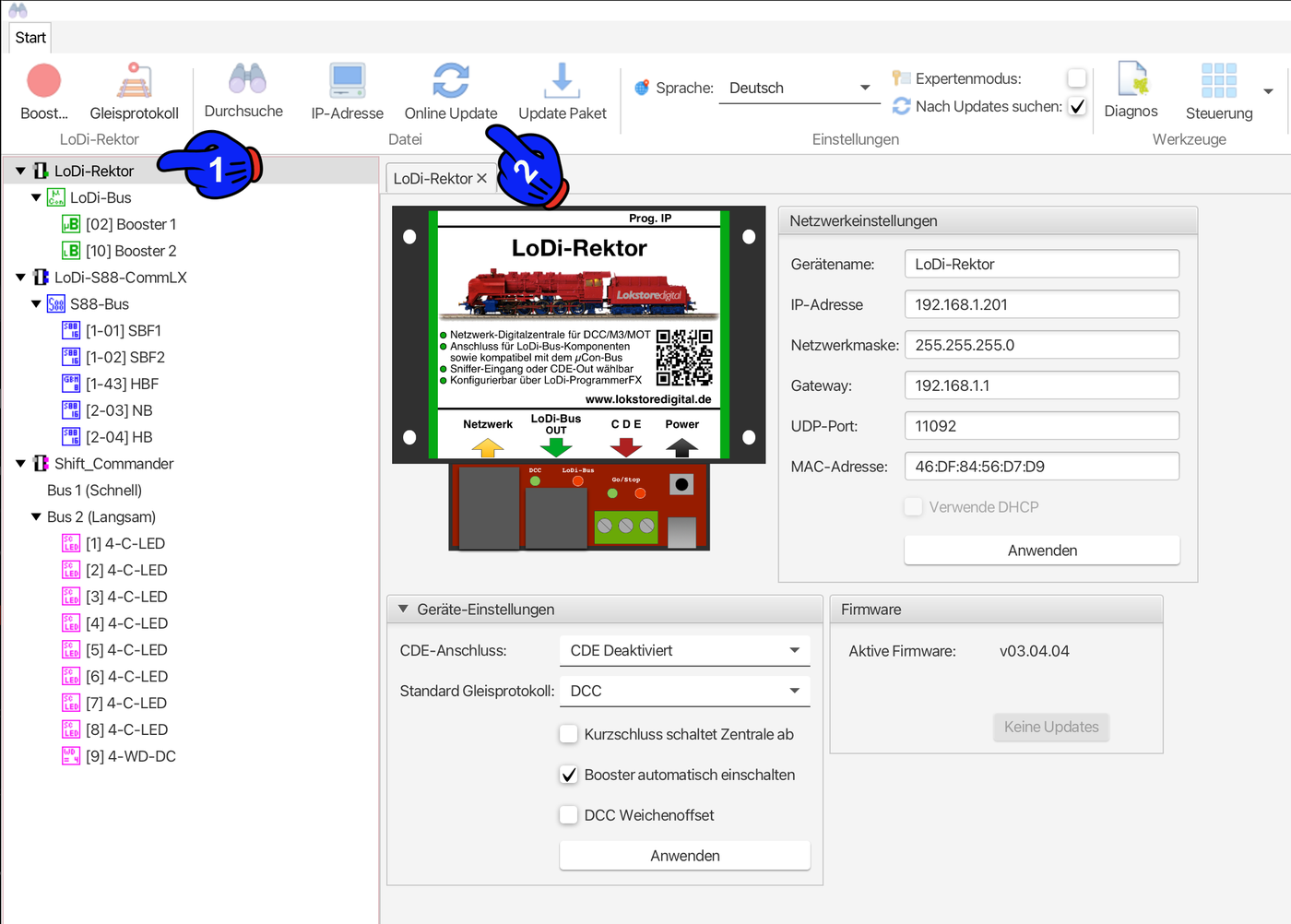
First click the device that is to be updated, in this case the LoDi-Shift-Commander (1). A new menu item now appears in the bar at the top: "Online-Update".
The update dialogue opens and the server automatically searches for available updates.
Then select the newest version shown (3) and click Install update (4). In the next dialogue the currently installed version and the version to be installed are shown to you once more.
Confirm the process by clicking OK to start the update. Once the update is finished, the device restarts automatically. If the current version is already installed, the LoDi-ProgrammerFX will say so.
3. LoDi operators
See LoDi operators and LoDi-Light-Operator

Any questions still open?
Would you simply like to ask us in person?
Or go to our forum, where experienced users are glad to help you further.
In this section
- LoDi-Light-Operator 4-C-LED
The LoDi-Light-Operator 4-C-LED serves to control the room lighting. Three 24-hour light curves as well as various additional effects can be configured.
- LoDi operators
LoDi operators drive actuators such as turnouts, signals, lamps or LEDs. Depending on the design, they have 8 to 32 outputs. In the LoDi-ProgrammerFX all normal LoDi operators are operated through the same interface. Special operators such as the [LoDi-Light-Operator 4-C-LED](docs:sw-lodi-light-o…