Getting started
Digital operation
This variant offers the most comfort and the greatest safety for your models. The model railway software knows exactly where a locomotive or a train is. If you re-rail a locomotive, the computer knows immediately where it is. Long hunts for short circuits on the layout are a thing of the past, because our technology shows you in the software exactly where the short is.
1. The locomotives and the data format
The most common question is of course: can I keep using my vehicles?
Yes of course — although you should convert your locomotives either to MFX or to DCC with RailCom if they still speak Motorola.
(Would you rather not give Motorola up? Then click here.)
First we have to check whether we can add to or change the technology in the locomotives.
- For Märklin locomotives with MFX that can do DCC, please set them to DCC and fit a RailCom transmitter.
- For Märklin locomotives with MFX older than 2018, you should fit a RailCom transmitter and give it an address of its own. The locomotive is then addressed in the system with an MFX UID and a DCC address.
- For locomotives with DCC — Brawa, Roco and the like — you should check whether they already do RailCom. If yours does not, we recommend a more recent decoder or fitting a RailCom transmitter.
- For locomotives with Motorola: please convert to DCC RailCom or MFX — or grant them a life in the display cabinet ;)
Once the locomotives have been checked and it is clear which principle to go with, we recommend running everything in DCC, or in DCC and MFX, for the sake of driving comfort.
2. The track system
Since we are talking about three-rail track here, we should of course briefly mention the kind of track system.
Looking at Märklin® three-rail track, there are 3 variants:
1. C track
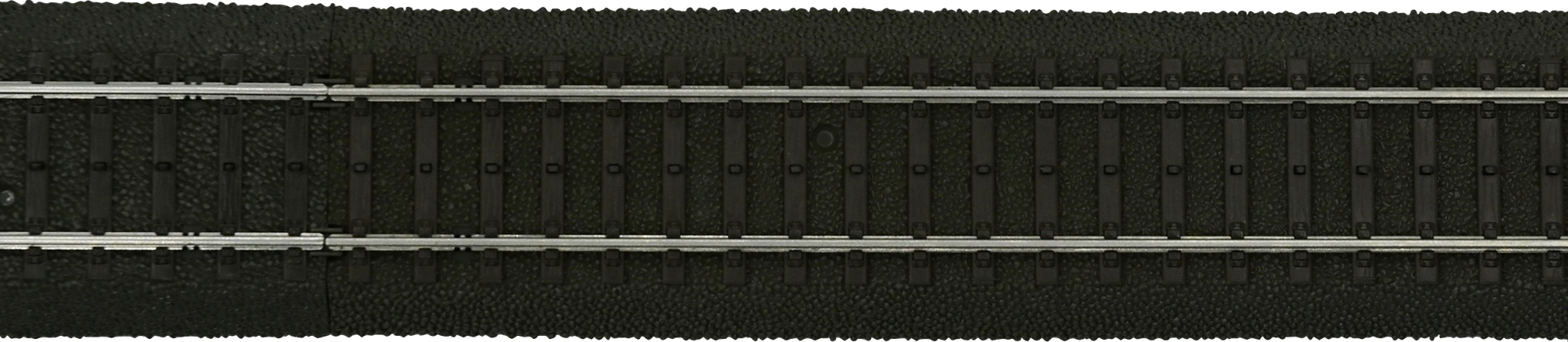
C track is a popular choice where running reliability in hidden yards matters. It is an absolutely top-class track when it comes to play layouts where the scenery is secondary. Reporting carriages is a little more involved here, because on C track two contact tabs have to be separated to isolate the left rail profile from the right. Only then can a feedback system be run on C track, conventionally or with carriage detection.

2. K track
Probably the most common track system: a sturdy plastic-sleeper track that is a favourite in layout building. General vehicle detection is possible here without much effort.


3. M track
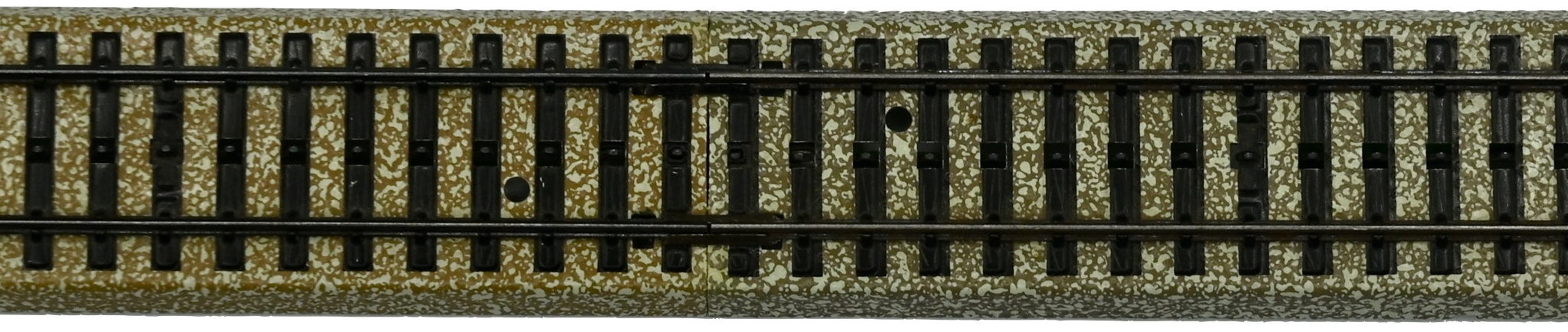
Once widespread, M track still has plenty of devotees.
It runs without any trouble on our system; here we report over the centre rail.
3. The first small setup
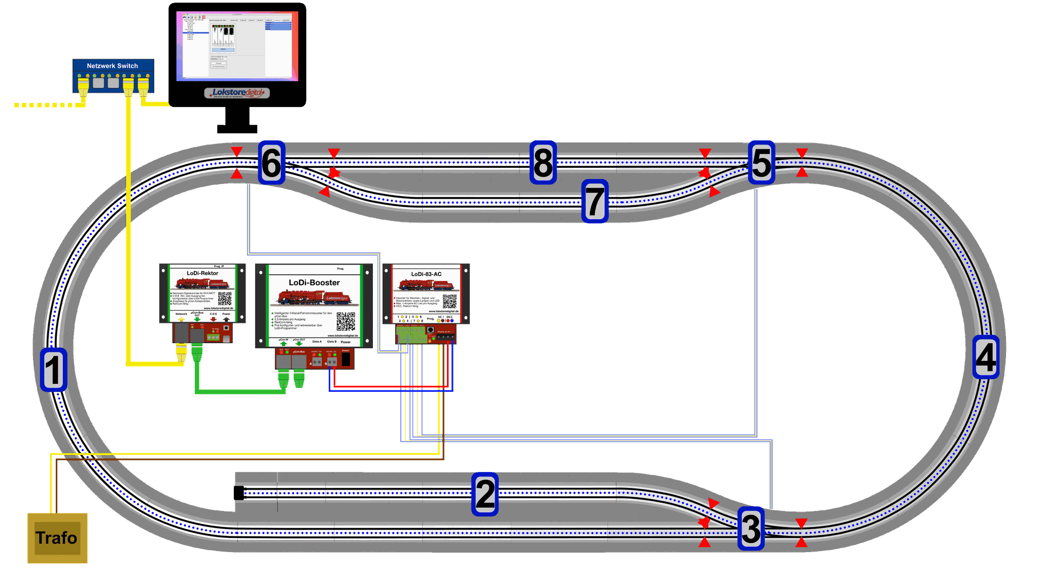
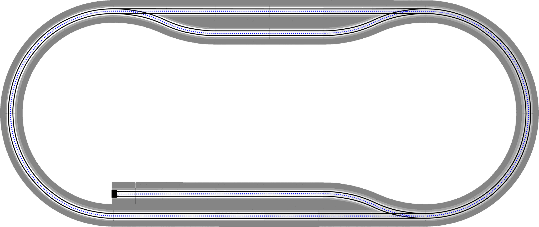
A small test layout is the best way to feel your way into all of this. That is why we use this small plan to show you which steps have to be taken where, to arrive at a fully computer-controlled model railway.
An example with C track. (Click the pictures to enlarge them)
The isolation points come later; for now the point is simply to run a locomotive in a circle.
Build this stretch on a small board. You can download the parts list and the track plan as a PDF right here:
4. The computer
First we need a computer to install the LoDi-ProgrammerFX on. That can be a Windows computer from Windows 8 64-bit onwards, a Linux machine such as Ubuntu, or a Mac from macOS 10.11.x onwards.
Java has to be able to run on the machine. Our LoDi-ProgrammerFX runs on Java 14 and newer.
The LoDi-ProgrammerFX for Windows and Linux ships with Java; all you have to do is install
the LoDi-ProgrammerFX.
You can control our components over a LAN — that is, wired — or from a laptop connected to the network over Wi-Fi (provided the Wi-Fi router has good signal quality).
The LoDi components then have to be on that network too. A combination of a desktop machine and a laptop is of course possible as well, and depending on the size of the layout it can be a great help.
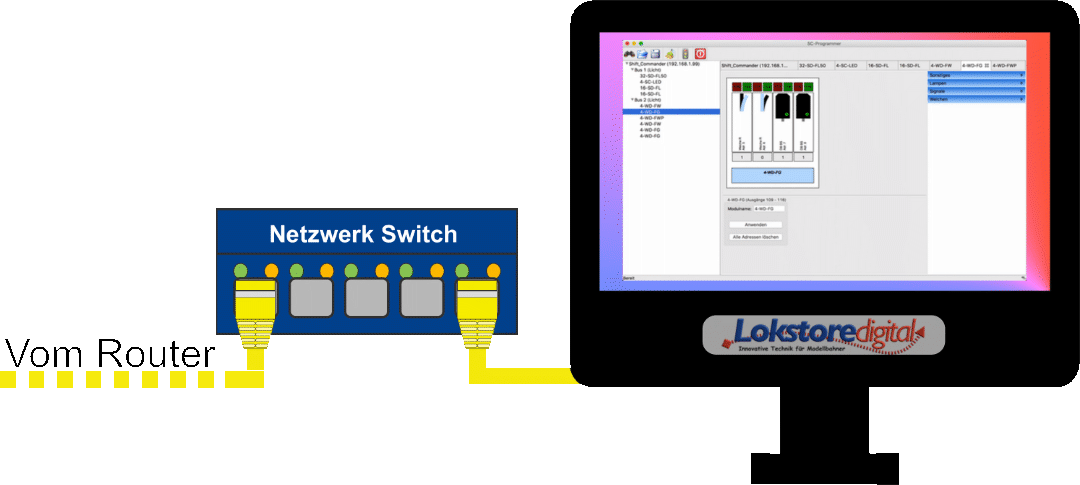
Here we show an example with a wired network connected to a router.
To find out how to configure an IP address for the LoDi-Rektor, LoDi-S88-Commander or LoDi-Shift-Commander, click here.
5. Driving
To begin with we want to get one locomotive running on the new system.
For that we use:
- The LoDi-Rektor as the command station; it speaks DCC, M3 and Motorola. In this example we use DCC only.
- The LoDi-Booster, a double booster that delivers 2 track sections with 2.3 amps each, or up to 5 amps when combined.
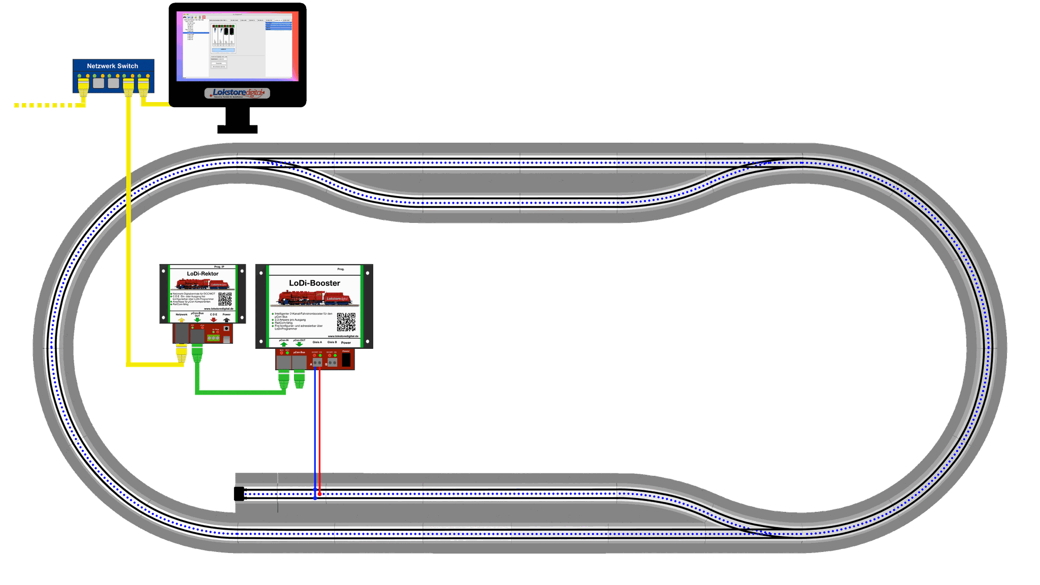

First we mount the devices on the board. Then we connect the LoDi-Rektor and the LoDi-Booster to their power supplies (included in the delivery).
After that the patch cable for the IP network is plugged in. This can now be connected to your home network through a switch.
Now we connect the LoDi-Rektor to the LoDi-Booster over the µCon bus; these are joined with a green patch cable.
Every device has its own colour and an arrow marking. To find your way around the layout more easily, we recommend sticking to this colour code. The µCon bus terminator supplied is the last thing to be plugged into the µCon Out socket of the LoDi-Booster.
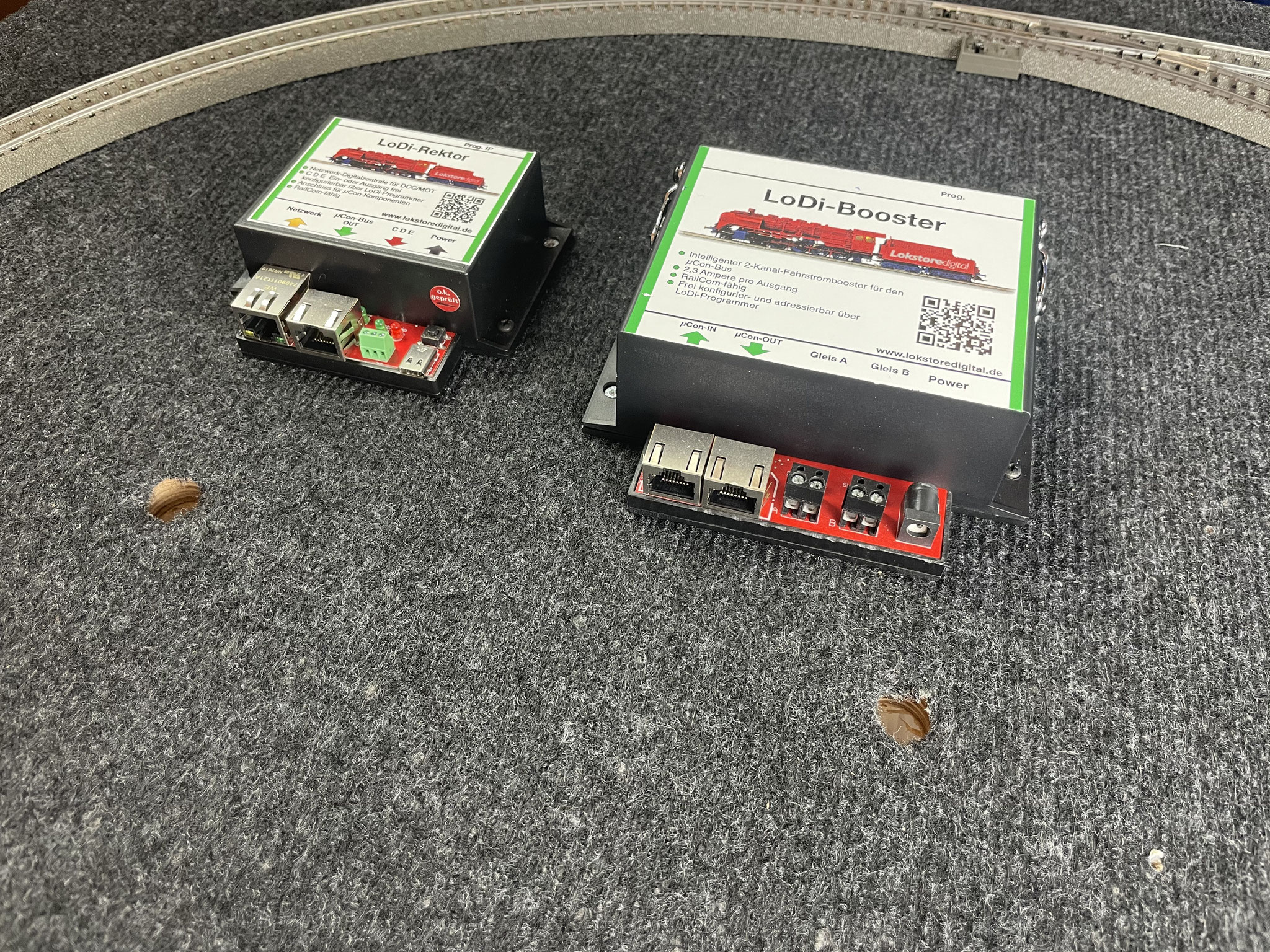

Now that the Rektor and the Booster are connected, we can wire up the track.
For that we use a 0.75 mm² cable.
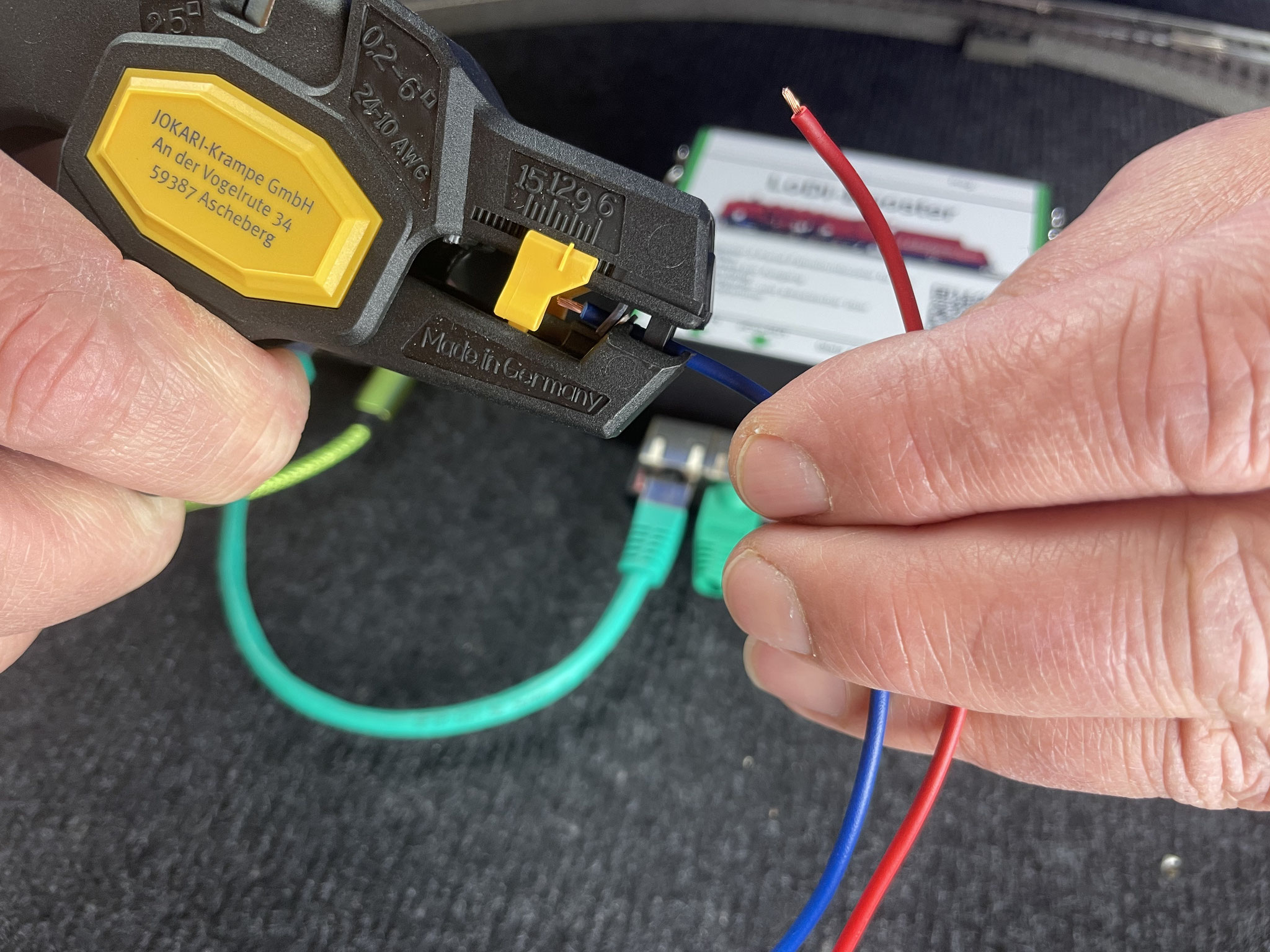
We strip one end of the cable with a stripping tool and use a 0.75 mm² ferrule. The ferrule is easily crimped with a ferrule crimper.
Now we cut the cable to length and solder it to a piece of track — in this case we fed the power in at the siding. That is enough to get a locomotive running briefly.

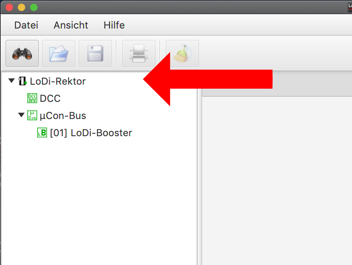
We have now connected every device, hooked up the power and put the LoDi-Rektor on the network. (If the LoDi-Rektor is not configured yet, click here)
The LoDi-ProgrammerFX now shows you the LoDi-Rektor on the left-hand side.
In this configuration we use, as described above, a network switch, a PC and — if there is one — an internet connection.
The LoDi-ProgrammerFX now serves as the driving software.
The LoDi-Rektor can also be used directly with control software such as iTrain or WinDigipet. Please note that the LoDi-ProgrammerFX is not an automation system: it exists to monitor and configure the LoDi products.
For this first test we use a locomotive with a DCC decoder that has RailCom.
The overview in the LoDi-ProgrammerFX shows the connected LoDi-Booster alongside the LoDi-Rektor.
Clicking a device takes you to its settings. We will not go into detail here — we want to get a locomotive running. If you want to know more about configuring the devices, click here.

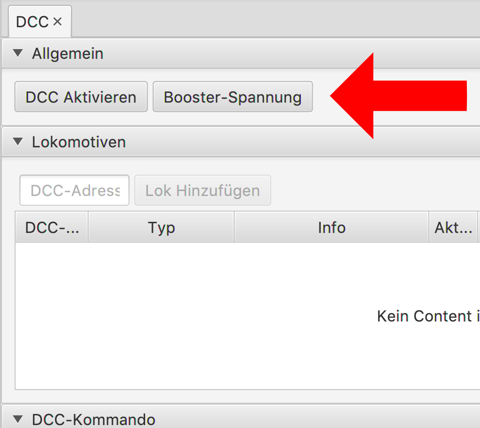
Now we click the DCC tab.
A dialog opens in which we can drive locomotives, throw turnouts and programme DCC CVs (PoM).
First click the "Activate DCC" button and then "Booster voltage".
The buttons turn dark green and are now active. Both green LEDs on outputs A and B of the LoDi-Booster should now be lit.
Now we enter the address of our DCC locomotive in the "DCC address" field. Press "Add locomotive" and the address is entered into the locomotive list.
The locomotive can now be driven from the "DCC commands" menu, and its functions switched.


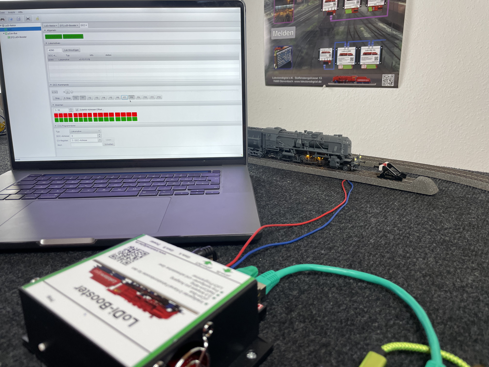
We have successfully got a locomotive running with the LoDi-Rektor and the LoDi-Booster. To close this chapter, one more thing:
The LoDi-ProgrammerFX does not replace control software. It exists to configure and check the LoDi components. It can also be used to drive locomotives and throw turnouts, but our aim here was only a quick test, not proper operation.
The LoDi-ProgrammerFX is developed continuously and keeps gaining new functions from us. If something is missing for you, talk to us, or turn to our forum.
6. Switching
The next thing we turn to is throwing the 3 turnouts on our test layout. As this is only a small layout, we went for the LoDi-83-AC in this variant. It is a turnout decoder that works over the DCC protocol.
Should your layout grow larger, we recommend switching over our SC system with the operators and the LoDi-Shift-Commander. That gives you a high-performance switching bus of its own, on which you can run a total of 230 turnouts using the LoDi-Operators 4-WD-AC, for example.
But back to the matter at hand.
The LoDi-83-AC and its sibling the LoDi-Operator 4-WD-AC switch alternating current. Together with the solenoid drives of most manufacturers that is a perfect combination. Our outputs therefore switch genuine AC and not, as most decoders on the market do, DC.
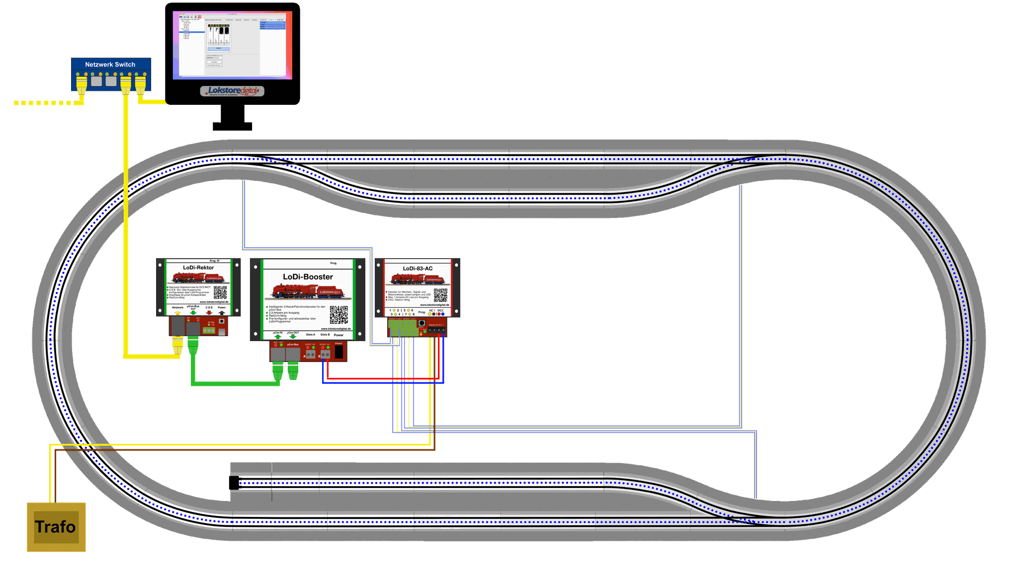

First we install our LoDi-83-AC on the board next to the LoDi-Booster.
If you have not installed any turnout drives yet, now is the time; in our example we went for the original C-track drives.
We connect track output B of the LoDi-Booster to the DCC input of the LoDi-83-AC.
The LoDi-83-AC absolutely requires an AC transformer for its power supply!!! It must not be fed with DC. There is more on this in the wiring examples for the LoDi-83-AC.
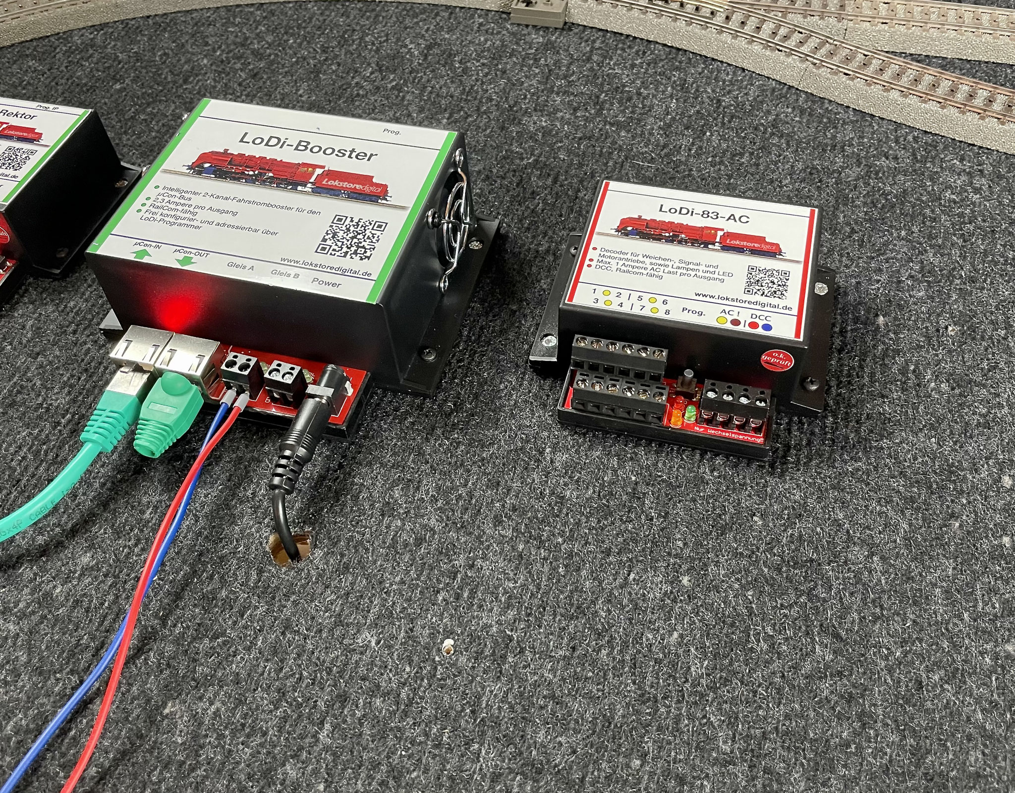
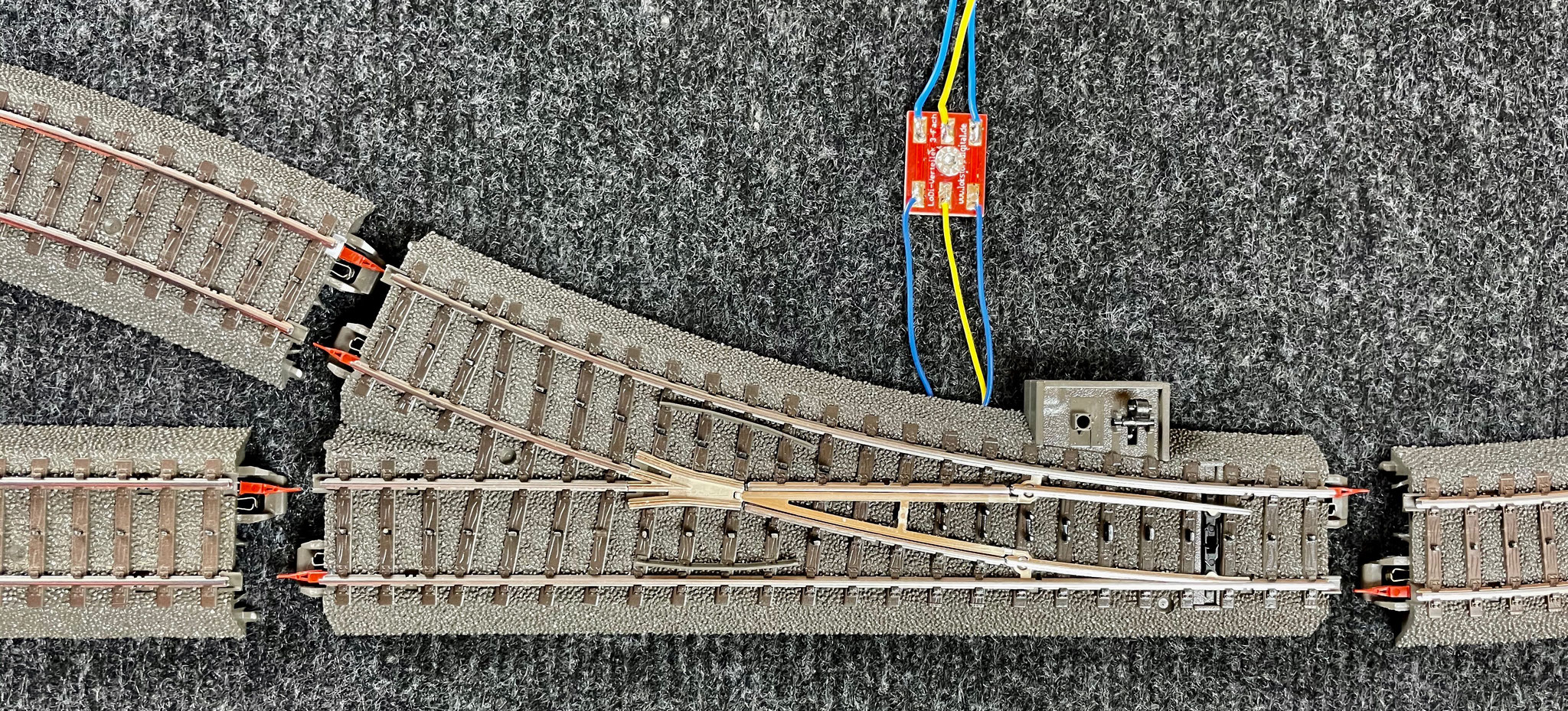
As a cable junction on the way to the turnout we recommend our LoDi distributor, 3-way. You are of course free to use other junctions.
Now we connect our 3 turnouts to the LoDi-83-AC, using a 0.25 mm² cable which we again crimp with the matching ferrules.
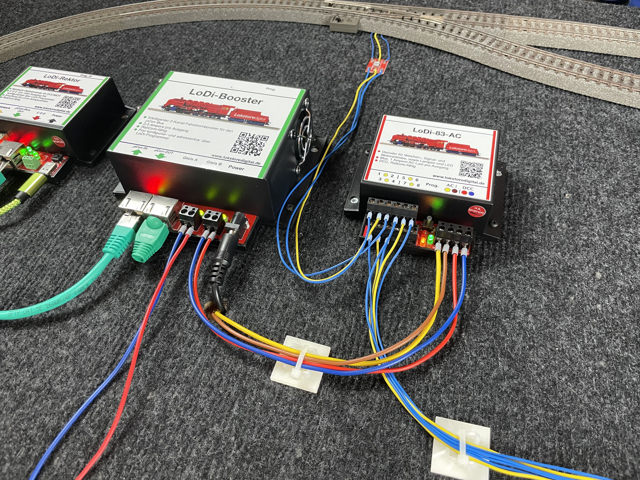
The decoder is connected now, and the LEDs show that it is ready.

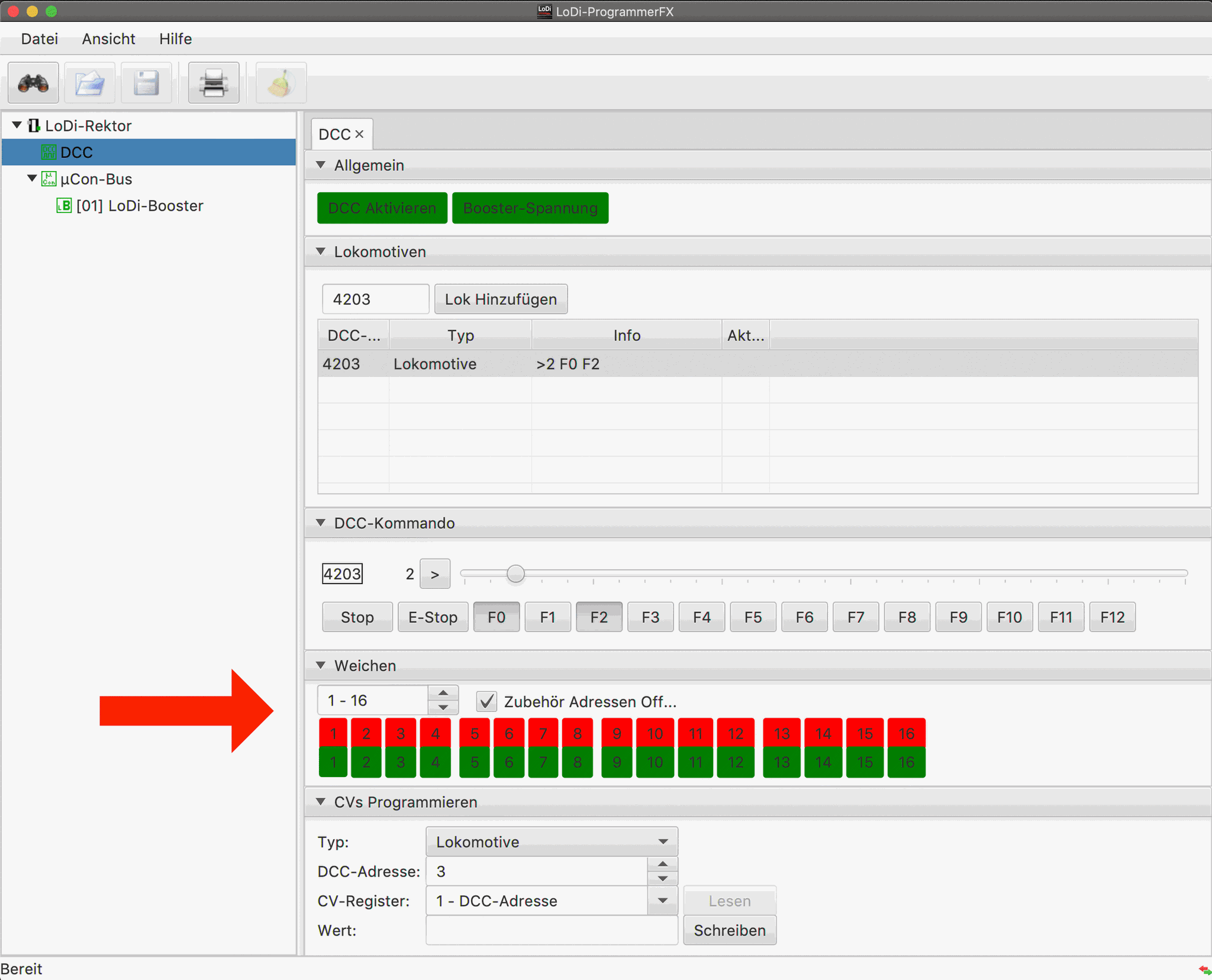
The LoDi-ProgrammerFX has a tab called "Turnouts". Every DCC turnout decoder can be driven from it.
The LoDi-83-AC is programmed to addresses 1 – 4 as delivered; pressing red and green in turnout fields 1 – 3 should now throw the 3 turnouts back and forth.
The CV programming tab also lets you adjust the switching times of the LoDi-83-AC comfortably — although the decoder's default settings are already ideal for solenoid drives.
7. Feedback
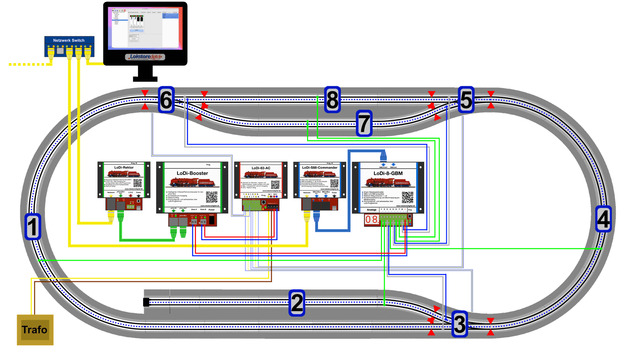
The basic prerequisite for a computer-controlled railway is feedback, which we implement with the LoDi-S88-Commander and the LoDi-8-GBM. This becomes the eye of the computer.
The computer can only sensibly control what it can see.
In the earlier — the old — variant, feedback modules were simply triggers, set off by a connection to ground.
Think of it like a light switch. You walk into a room and turn the light on. Nothing else happens when the locomotive enters a block, or, in the comparison, enters the room.
But here we have the biggest change compared with the old systems. Not only reporting axles, but capturing the locomotive's data in the block — in the feedback module — is new in these decoders. On top of that this variant gives us short-circuit detection down to the block, which three-rail operators in particular benefit from a great deal.
The LoDi-8-GBM actually comes from two-rail operation, where it is used as an occupancy detector by measuring current.
So why not use that technology on every three-rail layout as well?
That is exactly where we come in.
You could of course already report M track to the LoDi-8-GBM before — although on M track only the centre rail can be reported, which is no problem in itself, but it means no carriages are detected and locomotives are only seen through the pickup shoe.
With C and K track it is a little different: here we can use the rail profiles as the measuring point, and carriage detection on both of these track systems is perfectly possible with the LoDi-8-GBM too. The turnouts are monitored along with everything else, so the computer can see when 2 locomotives are in one turnout street and stop them.
So what do we have to change for that?
There is a detailed description of this in the manual of the LoDi-8-GBM; please scroll to point 7, “Connecting the LoDi-8-GBM to three-rail track”.
We will go over it briefly here as well.

From now on we use the centre rail as ground. That means we no longer break the centre rail anywhere on the layout — in the LoDi system all grounds may be connected, since the blocks already separate all the profiles, the blocks and the turnouts from one another anyway.
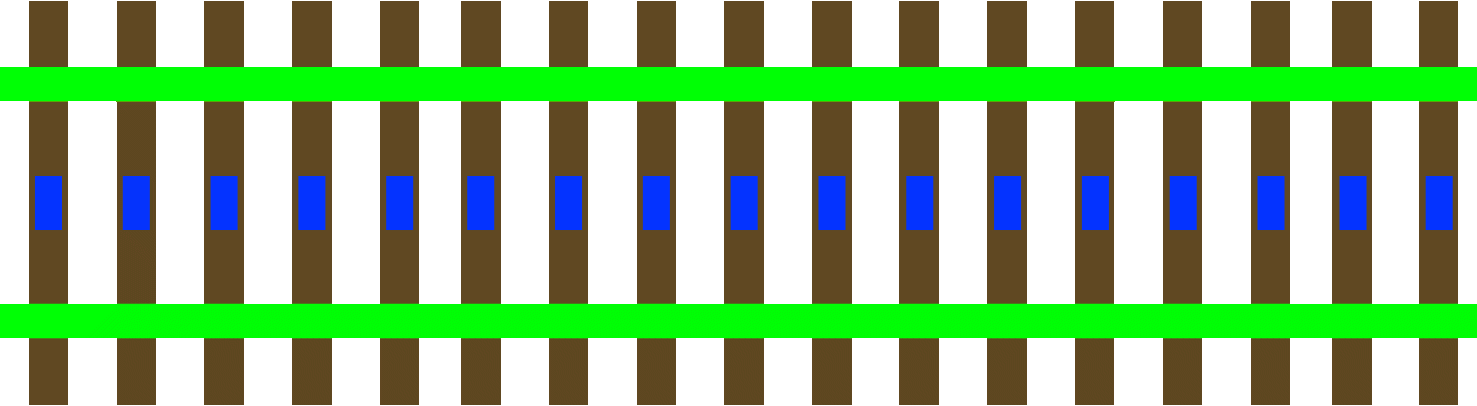
In this example you see a form of detection we already use in many layouts today. It picks up the first current-carrying wheel that touches the block and can generate feedback from it directly.
This variant does not detect carriages yet, but that comes on top in the next chapter.

Let us start with dividing our small test layout into blocks. In our example we use one feedback module per block. Once the locomotives are all well adjusted and measured in, this variant can control entire halls of layouts. If the software you use needs several detectors per block, you have to adjust the number of detectors for your software: you may need an entry, a braking and a stopping detector. In our example we use iTrain, which gets along well with one detector per block.
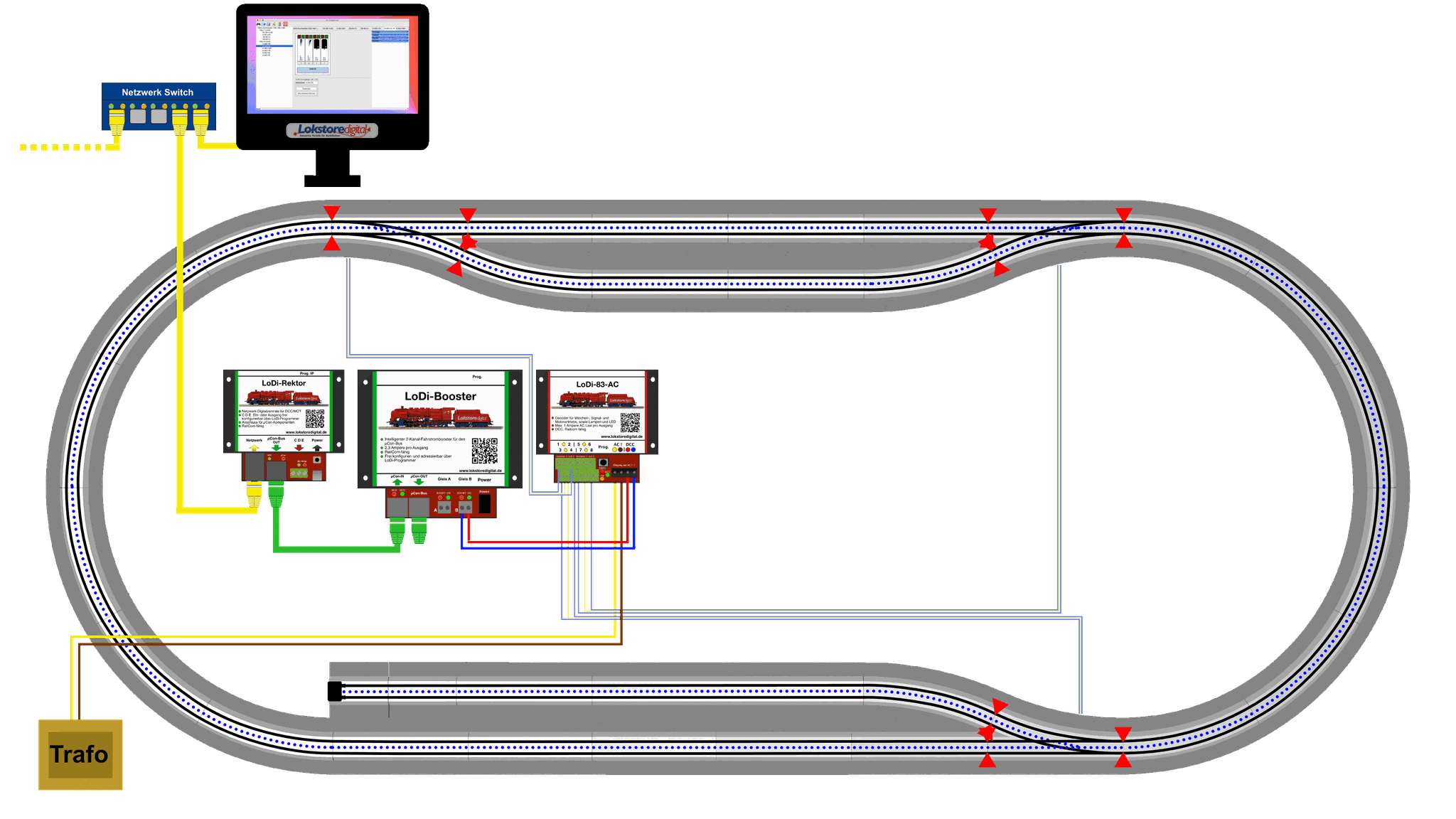
Now we separate the rail profiles on the right and left sides directly at the turnouts and on the tracks, using the matching insulating shoes for C track. If you use K track, we recommend insulating rail joiners.

For our example we now need 18 insulating shoes; if you have fitted them as in the drawing above, the result is 8 feedback contacts.